
Li-ion Battery Separator Technology White Paper 2025
I. The essence of lithium-ion battery diaphragm: more than physical isolation
As one of the four core materials of lithium-ion batteries, diaphragm bears two key missions:
1. Mechanical isolation barrier: physically isolates the positive and negative electrodes, preventing internal short circuits (e.g. dendrite puncture).
2. Ion transport channel: Its microporous structure allows Li⁺ to migrate efficiently while blocking electronic conduction (electronic insulation).
Engineer’s Perspective: Diaphragm performance directly determines the safety boundary, power output and cycle life of the battery, and is the “silent guardian” in the design of the battery cell.
II. Eight core engineering requirements for lithium-ion battery diaphragm design
In order to meet the demands of complex electrochemical environments, high-performance diaphragms need to meet the following stringent conditions:
| Required category | engineering implications | risk of failure |
|---|---|---|
| electrical insulation | Body resistivity >10¹⁴ Ω·cm, completely blocking the passage of electrons | Increased self-discharge, capacity degradation |
| ionic conductivity | Microporous pore size 0.01-1μm, porosity 30-50%, ensuring low resistance ion migration. | Increased internal resistance, decreased multiplication performance |
| Electrochemical stability | Resistant to 4.5V+ high voltage and EC/DMC polar solvent corrosion (ΔG <0) | Membrane degradation, pore collapse, short circuit risk↑ |
| electrolyte wettability | Contact angle <15° (actual measurement), liquid absorption rate ≥130%, long-lasting liquid retention capacity | Increased interface impedance and reduced cycle life |
| Mechanical integrity | Puncture strength ≥300 gf/μm, tensile strength MD/TD >100 MPa (ensuring process yield) | Assembly damage, burrs causing thermal runaway |
| Dimensional stability | Heat shrinkage rate (90°C, 1h) MD/TD <5%, curvature ≤3mm/m | Electrode sheet wrinkling, abnormal local current density |
| thermal protection mechanism | Closed-cell temperature 130-140°C (rapidly blocks ion flow), melting temperature >160°C (maintains structural strength) | Thermal runaway propagation, safety protection failure |
| Uniformity assurance | Thickness tolerance ±0.1μm, surface density fluctuation <3% (SEM verified hole distribution) | Poor battery consistency, batch yield fluctuations |
III.Analysis of Key Performance Indicators: From Lab to Mass Production
Diaphragm performance needs to be verified through systematic testing, and the following are the 9 core indicators that affect battery performance:
1. Structural homogeneity (SEM + thickness/ surface density)
Significance: Observation of microporous morphology (round/slit), distribution uniformity, thickness fluctuation control.
Engineering Implications: Determines current distribution uniformity and risk of lithiation. For example, uneven pore size distribution can lead to localized high Li⁺ flux and induce dendrites.
2. Ion Transport Efficiency (permeability + porosity + ionic conductivity)
Test methods: Gurley value (s/100cc), porosity by pressed mercury method, ionic conductivity (>1 mS/cm) by EIS.
Engineering Impact:
Low Gurley value (<200 s) → fast charging capability enhancement (e.g., power battery demand)
High porosity (>40%) → lower interface impedance, but need to balance mechanical strength
3. Interfacial compatibility (wettability + liquid absorption rate)
Quantitative criteria: electrolyte contact angle <15°, liquid absorption rate ≥130% (1h immersion).
Engineering Impact:
Excessive contact angle → insufficient electrolyte filling → interfacial side reactions ↑
Insufficient liquid absorption → electrolyte depletion in cycle → capacity diving
4. Mechanical Reliability (Puncture Strength + Tensile Strength)
Test Criteria:
Puncture Strength: Simulate wafer burr (≥ 300 gf/μm)
Tensile Strength: Guarantee coating/winding yield (MD/TD > 100/50 MPa)
Failure Cases: Insufficient Tensile Strength → Film Tear during Winding → Core Scrap Rate ↑5%.
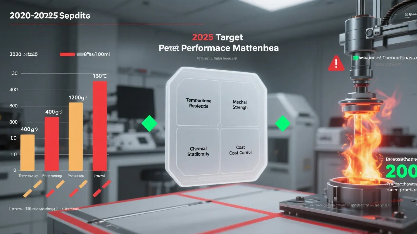
5. Thermal Safety Performance (Thermal Shrinkage + Closing/Melting Temperature)
Safety Thresholds:
Thermal Shrinkage (90°C): MD <4%, TD <2%
Closed Hole Temperature: 130-140°C (e.g. PE based diaphragm)
Melt Temperature: >160°C (e.g. PP based or ceramic coated diaphragm)
Protective Logic: When temperature rises suddenly, closed holes block the ionic flow → Melt maintains the structural integrity → Enable safe escape time.
6. Long-term stability (tortuosity + chemical stability)
Tortuosity:
Ideal: 1.5-2.5 (lower values mean straighter ion paths)
Impact: High tortuosity → Li⁺ migration path lengthened → internal resistance ↑
Chemical Stability: Need to withstand HF corrosion (LiPF₆ decomposition products) to prevent membrane embrittlement.
IV. Cutting-edge trends: the next generation of diaphragm technology direction
1. Coating technology:
- Ceramic coating (Al₂O₃/SiO₂): Improvement of thermal stability (melting point ↑30-50°C) and resistance to dendrites
- Polymer coating (PVDF/PMMA): Enhancement of electrolyte affinity (contact angle ↓ to 5°)
2. Base film innovations:
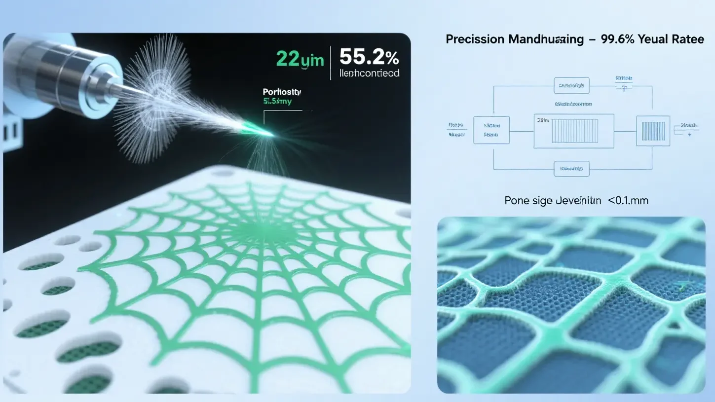
- Ultra-thin high strength film: 5μm base film puncture strength >400 gf/μm (e.g. Asahi Kasei Hipore™)
- Nanofiber diaphragm: 3D network structure → Liquid Absorption >200% (startup applications)
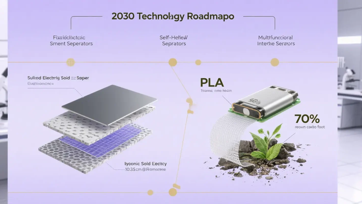
3. Smart diaphragms:
- Temperature-responsive polymers: hole closure accuracy ±2°C (improves thermal shutdown reliability)
- Self-healing coatings: in-situ healing of microcracks, extends cycle life >20%)
Engineers assert that the diaphragm is evolving from a “passive isolation layer” to an “active safety controller” – when the pore closure response speed breaks through the 10ms level and the temperature resistance crosses 250℃, the safety of lithium batteries will be revolutionized. Lithium battery safety will usher in a revolutionary breakthrough.