
Battery Solution Performance for Robotics: A Field
When a procurement manager asks me for a “robotics battery,” they are usually picturing a laptop cell in a bigger box. After fifteen years specifying custom battery solution programs for warehouse Autonomous Mobile Robots (AMRs), articulated arms, and humanoid platforms, I can tell you the robotics duty cycle is one of the harshest a lithium battery will ever see. A robot does not glide at a steady cruise like a drone — it punches joints, brakes, regenerates, and repeats that burst profile thousands of times per shift. This article is the specification guide I wish every robotics engineering team had before they sourced their first pack. If you are also weighing airborne platforms, the same fundamentals apply to a drone battery, but the mechanical and certification envelope is tighter on the ground.
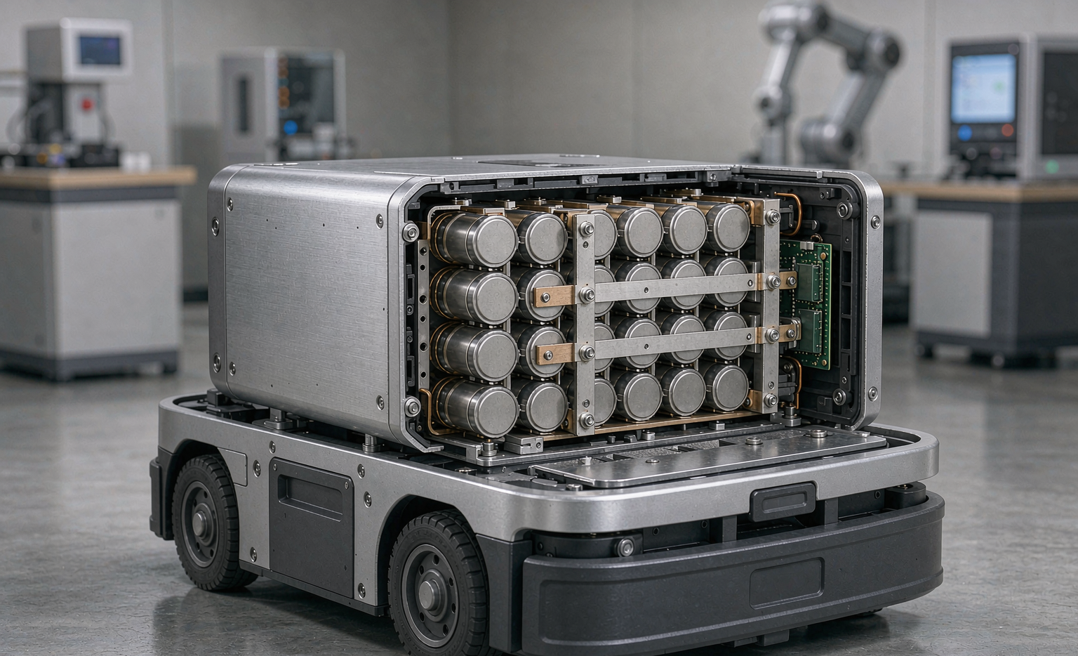
Why Robotics Is a Different Battery Problem
A warehouse AMR or a six-axis arm is not an energy-storage device with a motor bolted on — it is a power-electronics system whose loads are dominated by short, asymmetric, high-current pulses. Each joint servo can demand 5–15 C for 200–800 ms during acceleration, then sink current back during deceleration. A custom battery solution for robotics therefore has to be tuned for power availability under simultaneous multi-axis load, not just rated capacity.
In my lab I treat the pack as the last stage of the powertrain. Cells → busbars → BMS → thermal path → connector. A 1% rise in internal resistance (DCIR) shows up at the joint as visible sag and slower settle time long before the robot “runs out of charge.” That is why we grade cells and measure DCIR with four-wire Kelvin methods on every incoming lot.
Energy Density vs Power Density — Reading the Duty Cycle
The first decision is cell chemistry, and the trade is between gravimetric energy density (Wh/kg) and power density (W/kg). For a mobile robot carrying its own mass, every kilogram of pack is a kilogram you cannot spend on payload.
- NMC 21700 (high-energy): ~250–280 Wh/kg cell, 1500–2200 W/kg continuous. Good default for AMRs with long travel and moderate joint loads.
- NMC high-power variant: ~200–230 Wh/kg but 2500–3500 W/kg pulse. Use this for dynamic humanoids and pick-and-place arms where burst current dominates.
- LFP (LiFePO₄): ~160–190 Wh/kg, 1200–1800 W/kg, but 2000–4000 cycles. The right call when calendar life and thermal margin beat energy density, e.g. slow tuggers running three shifts.
The mistake I see most often is over-specifying Wh/kg. A pack sized on label capacity but starved for W/kg will trip its BMS current limit during a coordinated full-body motion. Size the pack to the peak pulse envelope, then confirm the resulting energy budget still meets shift runtime.
Voltage Sag and Pulse Handling Under Actuator Loads
Voltage under load is V = Voc − I × R_int. At a 6S (22.2 V nominal) pack drawing 60 A through a 7 mΩ pack DCIR, you lose ~0.42 V instantly — about 2% — but at a 120 A actuator punch through a marginal weld that becomes 0.84 V, and the servo bus droops. We retire packs when DCIR climbs >30% from formation baseline or cell-to-cell spread exceeds 40 mV, because that is the point where sag becomes a motion-quality problem rather than just a runtime problem.
Design levers that actually move the number:
- Pure-nickel laser welds held under 0.15 mΩ per joint, verified by X-ray and pull-test (>25 N).
- Parallel grouping (e.g. 6S2P → 6S3P) to halve per-cell current and halve pack DCIR.
- Short, wide busbars with low-L routing to keep inductive droop off the servo bus during 200 ms pulses.
I log per-pack DCIR at every formation cycle and stamp it into a DataMatrix genealogy tag. Two years later, when a fleet robot starts “stuttering” on a pick, that one number tells me whether the pack or the gearbox is at fault.
Cycle Life and Opportunity Charging for Multi-Shift Fleets
A robotics fleet lives or dies on throughput, so charging strategy is a performance parameter, not an afterthought. We design for opportunity charging: 10–15 min top-ups to 80% during breaks, rather than one daily full charge. That shifts the wear model from deep cycling to partial-state-of-charge (PSoC) micro-cycles.
Typical qualified results from our programs:
- NMC packs: 800–1500 cycles at 80% DoD, or 2000+ equivalent PSoC micro-cycles.
- LFP packs: 2500–4000 cycles, the reason slow tuggers outlive their AMR siblings.
- Charge window: 10–45 °C pack temperature; below 10 °C we derate to 0.3 C and lower termination voltage to avoid lithium plating on the anode.
The economics are real: a 10-minute opportunity charge between shifts replaces one spare pack per robot with a charging pad. On a 50-robot fleet that is 50 fewer packs to buy, store, and track.
Thermal Envelope and Cold-Weather Performance
Robotics packs run in unconditioned warehouses and outdoor yards, so the thermal envelope is a performance contract. Our standard spec is −20 → 60 °C discharge, 0 → 45 °C charge, with a 55 °C core hard-limit and a two-stage BMS derate (trim at 45 °C, hard stop at 55 °C).
Cold is the quieter killer. Below 0 °C, NMC capacity holds but power fades 20–30% at −10 °C and pulse capability collapses — a humanoid that walks fine at 20 °C may squat and fail to stand at −10 °C. We address it with a conduction path (aluminum spreader at ~230 W/m·K plus 1.5–3.0 W/m·K thermal interface material) and, for yard robots, a low-watt self-heat band that holds cells above 5 °C during standby. DCIR measured cold is the gate: if it climbs >60% from the 25 °C baseline, the pack is not cleared for winter duty.
Safety Architecture for Human-Collaborative Robots
Once a robot shares a workspace with people (ISO/TS 15066 collaborative regime), the battery stops being a component and becomes a hazard source you must bound. My non-negotiables:
- Ceramic-coated separator with 130 °C thermal shutdown as the cell-level firewall.
- BMS dT/dt early-warning on every cell group, tripping the contactor in <200 ms on a runaway slope — not just on over-temperature.
- Mechanical isolation: hard-anodized 6061-T6 cradle, keyed anti-misinsertion connector, and a peripheral crush zone so a dropped arm or a forklift bump loads the case, not the cells.
- Pressure-equalization vent with flame arrestor for sealed enclosures.
This is where a custom battery solution earns its premium. A generic pack meets the shipping standard; a robotics pack has to meet the collision standard, which is a different and harder test.
Standards and Qualification You Cannot Skip
Every robotics pack we release clears the same qualification floor, because “it passed on the bench” is not a certificate. The core stack:
- UN38.3 (T.1–T.8): altitude, thermal, vibration, shock, external short, impact, overcharge, forced discharge — the transport floor for any lithium cell. Note it proves the cell survives shipping, not that it survives a robot crush.
- IEC 62133-2: portable cell safety (short-circuit, overcharge, forced discharge, temperature).
- IEC 62619: industrial stationary/secondary cells — the relevant bar for warehouse and AGV packs.
- UL 2580: batteries for electric propulsion, widely demanded by North American integrators.
- ISO 3691-4 / ISO/TS 15066: driverless industrial trucks and collaborative robot safety — the application standards that actually govern a robotics deployment.
- FAA / EASA reference practices: for any airframe-adjacent or inspected UAV sibling program, we mirror the transport and operational framing even when the robot stays on the ground.
My rule to procurement: if a vendor cannot show UN38.3 T.1–T.8 plus IEC 62133-2 and IEC 62619 test reports, the pack is not qualified regardless of how good the datasheet looks.
Frequently Asked Questions
What battery chemistry is best for warehouse robots?
For most AMRs and tuggers, NMC 21700 hits the sweet spot of energy and power density. Choose LFP when cycle life and thermal margin outweigh mass — slow three-shift tuggers are the classic case. Humanoids and fast pick-and-place arms usually need a high-power NMC variant for burst current.
How do I stop voltage sag from slowing my robot’s joints?
Size the pack to the peak pulse current, not the average. Use parallel cell grouping to halve pack DCIR, keep pure-nickel laser welds under 0.15 mΩ, and retire any pack whose DCIR rises >30% from formation baseline. Log DCIR per pack so motion faults are diagnosable months later.
Can robotics batteries use opportunity charging?
Yes, and it is usually the right design. 10–15 minute top-ups to 80% between shifts convert a deep-cycle wear model into gentle PSoC micro-cycles and cut spare-pack count dramatically. Keep the charge window at 10–45 °C and derate below 10 °C to protect the cells.
Which safety standards matter most for collaborative robots?
UN38.3 T.1–T.8 plus IEC 62133-2 and IEC 62619 form the qualification floor; ISO 3691-4 and ISO/TS 15066 govern the actual collaborative deployment. Layer on a dT/dt-aware BMS and mechanical crush isolation so a bump loads the case, not the cells.
How cold can a robotics lithium battery operate?
Discharge holds to about −20 °C, but pulse power fades 20–30% by −10 °C. Charge only above 0–10 °C with derating to avoid lithium plating. For yard robots, add a low-watt self-heat band to keep cells above 5 °C during standby.





