
Battery Solution Integration for Vehicles
Why Vehicle Integration Is Where a battery solution Wins or Dies
When a procurement team buys a battery solution, they rarely buy a finished vehicle. What they buy is a pack, a BMS, and a promise that it will bolt into their chassis, survive the road, and talk to their CAN bus without setting off a fault light. In my fifteen years building custom battery solution programs for light-EVs, AGVs, and specialty vehicles, I have learned that integration — not the cell spec sheet — is where most field failures are born. A pack with perfect cells and a sloppy mounting bracket will rattle its welds loose in 4,000 km. A pack with a brilliant BMS and an unshielded harness will throw EMC errors the first time the motor inverter switches.
This article is the field guide I wish every OEM integration engineer had on day one: how we at Horizon Power treat vehicle integration as a disciplined, testable engineering phase, and the numbers we hold ourselves to before a pack ever sees a customer’s assembly line.
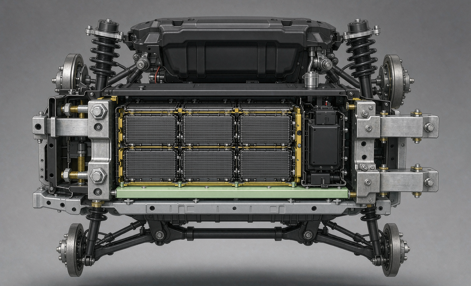
Mechanical Integration — Mounting, Crash Loads, and Vibration
The first question I ask a vehicle customer is not “how many amp-hours?” but “where does it sit, and what hits it?” A battery pack design that lives in a protected under-seat bay faces a completely different mechanical world than one bolted to a forklift frame over a potholed yard.
Our mounting baseline starts with the cell-to-pack structure. Cells are laser-welded with pure nickel at <0.15 mΩ and 25 N pull, held to Cpk ≥ 1.67 — the same joint discipline we apply to rugged lithium battery packs for industrial duty. The module then gets a 0.3–0.7 MPa preload against a cooling plate to keep thermal interface pressure uniform across every cell face. Brackets are sized to a 2.5× margin over the worst expected crash pulse (typically 8–12 g for the vehicle class), and every mounting bolt is torque-audited into the DataMatrix genealogy record.
Vibration is where cheap integration dies. We qualify the full assembly to MIL-STD-810H Method 514.8 (random vibration) and 516.8 (shock), sweeping 5–500 Hz with the pack powered and logging weld resistance drift. If a joint moves more than 5 µΩ across the profile, the design goes back, not to the line. This is the same ruggedization philosophy we apply when we build a drone battery for sustained flight vibration — the physics do not care what vehicle carries the cells.
Thermal Integration — Between the Cells and the Chassis
Mechanical contact is worthless if heat cannot leave the cell. Thermal integration is the handshake between the electrochemistry and the vehicle’s cooling loop, and it is the single most overlooked line item in a custom battery solution quote.
We specify a thermal interface material rated 1.5–3.0 W/m·K between every cell and the cooling plate, with compression controlled by the preload above so the bond line thickness stays within ±0.1 mm across the pack. The target is a cell-to-cell ΔT of less than 5 °C under the vehicle’s peak sustained load — beyond that, the BMS starts balancing against a thermal gradient instead of a state-of-charge, and cycle life suffers.
Chemistry choice sets your safety ceiling here. LFP (lithium iron phosphate) has a thermal-runaway onset around 270 °C; NMC sits near 210 °C. For a vehicle that might sit in a parked lot at 60 °C in summer sun, that 60 °C gap is the difference between a comfortable margin and a nervous one. We apply a charge lockout below 0 °C to protect the cells during cold-climate fast charging, and we size the vehicle’s coolant path so the pack never becomes the bottleneck on a hill climb.
Electrical Architecture — HV Bus, Contactors, Pre-Charge, and LV Harness
Integration electrical work splits into two worlds: the high-voltage (HV) bus that moves the energy, and the low-voltage (LV) harness that commands it. Get either wrong and the vehicle is either dangerous or dead.
On the HV side we run a 400 V or 800 V bus depending on the platform, with contactors rated 200–450 A DC and a pre-charge circuit that is non-negotiable. When the contactor closes on a cold bus, the capacitor bank on the inverter looks like a short; without pre-charge, you get an arc that welds the contactor shut. Our pre-charge resistor (50–200 Ω, sized to the bus capacitance) limits inrush to under 5 A and brings the bus to 90% of pack voltage within 300 ms before the main contactor picks. A high-voltage interlock loop (HVIL) runs through every connector so that any unplugged or loosened joint opens the contactors before anyone can touch live terminals.
The LV side lives by ISO 16750-2: it must survive 24 V transients, reverse polarity, and load-dump spikes to 40 V without the BMS rebooting. We use shielded twisted-pair for the signal lines and a TVS-protected loom so the pack is not the victim when the starter motor or inverter kicks. This is the same isolation discipline we bake into an aviation-grade drone lithium battery where a single harness fault is not an inconvenience but a crash.
BMS and Vehicle Network Integration
The battery management system is the only part of the battery solution that actually talks to the vehicle, so its network integration is where a pack feels “OEM-grade” or “aftermarket.”
We run a master-slave topology over CAN 2.0B, with slave boards on each module reporting cell voltage and temperature at 10 Hz and the master fusing it into a vehicle-facing signal. Current sensing is ±0.5% across a 0–1000 A range, insulation resistance is monitored continuously and flagged above 500 kΩ, and over-current protection trips in under 200 ms. A contactor weld-detect routine checks every close cycle, and a pyro-fuse stands behind the contactors for the fault that should never happen.
For on-road vehicles we design to ISO 26262 functional-safety expectations, targeting ASIL-C or ASIL-D on the safety-relevant paths, and we document the safety case the same way we document the cell grade. The BMS is firmware-hash-locked so a field “update” cannot silently change the protection envelope — a control we also apply to any lithium battery program where a software drift could void a certification.
Sealing, EMC, and Serviceability
The last integration layer is the one customers notice only when it fails: the enclosure. We seal to IP67 with an ePTFE breather that equalizes pressure without letting water or dust in, and we conformal-coat the control boards to IPC-CC-830B so humidity and condensation cannot crawl across a trace. EMC is qualified to CISPR 25 Class 3/4 and ISO 11452 immunity so the pack neither emits noise nor hears it from the inverter.
Serviceability closes the loop. Every pack ships with a DataMatrix genealogy that lets a dealer pull the cell grade, weld Cpk, and formation record from the serial number alone, and we design the enclosure so the BMS is a ten-minute swap, not a pack teardown. A custom battery solution that cannot be serviced is a liability the second it leaves warranty.
Frequently Asked Questions
What is the difference between a battery pack design and a full battery solution?
A pack design is the hardware — cells, enclosure, and BMS in a box. A battery solution includes integration: the mounting, thermal interface, HV/LV architecture, network protocol, sealing, and the test evidence that proves it survives the vehicle’s real duty. For a vehicle OEM, the solution is what actually goes on the bill of materials.
How do you prevent contactor welding during vehicle startup?
With a pre-charge circuit. A resistor limits the inrush current to under 5 A while the bus capacitors charge to 90% of pack voltage (typically within 300 ms), and only then does the main contactor close. We also run a weld-detect check every cycle so a stuck contactor is caught before it can arc.
Why does thermal integration matter more than cell choice for cycle life?
Because a 5 °C cell-to-cell gradient forces the BMS to balance against temperature, not state-of-charge, and that wastes capacity every cycle. Good thermal interface material and controlled preload keep the gradient under 5 °C, letting the chemistry deliver its rated 2,000–6,000 cycles instead of fading early.
Which standards apply to a vehicle battery solution integration program?
The floor we build to is UN38.3 (T.1–T.8 transport), IEC 62133-2 and IEC 62619 (cell and pack safety), UL 2580 (EV batteries), ISO 26262 (functional safety), IATF 16949 (automotive QMS), plus regional rules like GB 38031 and ECE R100. Transport and aviation cross-links follow IATA Section II at 30% SoC and FAA/EASA limits for any air-carried pack.





