
Battery Solution Maintenance for Robotics
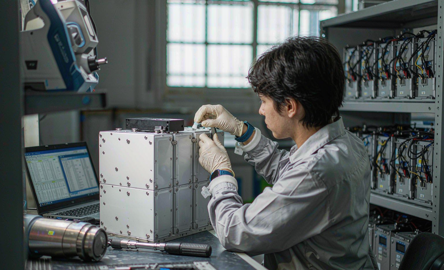
I have spent a large part of the last decade on the unglamorous side of robotics: not the launch, not the demo, but month fourteen, when a fleet of 120 autonomous mobile robots that behaved perfectly during acceptance testing starts dropping out of production with “battery fault” alarms that nobody can reproduce on the bench. Every one of those investigations eventually came back to the same root cause. Nobody owned maintenance. The pack was specified brilliantly, integrated carefully, and then left alone until it failed.
This article is the maintenance half of a robotics battery application solution. I have already written about how to specify performance, how to validate reliability, how to design, test, manufacture, and integrate a pack for a robot. All of those stages happen once. Maintenance happens every single shift for the next five to eight years, and in my experience it decides whether a fleet hits 95% availability or sinks to 70% and quietly becomes the reason the automation project never pays back.
What follows is the playbook I hand to fleet operators when they take delivery of a custom battery solution. It is deliberately specific: intervals, thresholds, torque values, and the four measurements that actually predict failure. Everything here is written for lithium chemistry in industrial and commercial robots, and I flag where the numbers change for LFP versus NMC or for semi-solid cells.
Why Robot Battery Maintenance Is a Fleet Availability Problem, Not a Pack Problem
The first mental shift I ask operators to make is this: you are not maintaining batteries, you are maintaining a service level. A single pack that loses 20% of its capacity is nearly invisible if the robot still completes its shift, because a well-sized pack carries 15-25% energy margin on day one. What is not invisible is a pack that trips its BMS on a peak-current event, or a hot-swap contact set that has worn to the point where it overheats, or a fleet where thirty packs reach 80% state of health in the same month because they were all commissioned in the same week and nobody staggered the replacement budget.
Robots are harder on batteries than almost any other application, and the reason is the duty cycle shape. A warehouse AMR does not discharge at a gentle constant current. It draws a 7-10 A baseline for traction and compute, then pulls 60-150 A for two to six seconds every time it accelerates, lifts a 500 kg payload, or regenerates into a deceleration. Those pulses do almost nothing to the cell’s temperature because the thermal mass absorbs them, but they do drive mechanical fatigue in every interconnection, and they do make state of charge estimation drift because the pack rarely sits still long enough for an open-circuit voltage correction.
Three consequences follow, and they define the whole maintenance programme:
- Failure is electromechanical before it is electrochemical. In the fleets I have audited, roughly 60-70% of “battery failures” were connector wear, loose terminations, or degraded thermal interface material, not aged cells. These are all cheap to catch and cheap to fix if you look.
- Capacity fade is the wrong primary metric. Internal resistance growth and cell-to-cell divergence predict an outage weeks before capacity fade does. A pack at 92% capacity with double its beginning-of-life DCIR will still trip under a lift pulse on a cold morning.
- Fleet synchronisation is a real financial risk. Packs commissioned together age together. If you buy 120 packs in month one and the chemistry gives you 3,000 cycles to 80%, you will face a six-figure replacement event in month forty-something, all at once. Staggering commissioning and rotating packs between high-duty and low-duty robots flattens that curve, and it is a maintenance decision, not a design one.
Building the Baseline: What You Must Record on Day One
You cannot trend anything without a baseline, and a surprising number of fleets start operating with no record of what “healthy” looked like. On commissioning day, for every single pack, I want five numbers captured and filed against the pack’s serial number:
- Beginning-of-life DCIR per cell and pack-level, measured at a defined state of charge (I use 50% ± 5%) and a defined temperature (25 °C ± 3 °C). Record both, because a resistance figure without a temperature is meaningless.
- Cell voltage spread at 40-60% SoC, in millivolts. A healthy new pack from a competent battery pack design should sit under 30 mV, and good production sorting gets you under 15 mV.
- Insulation resistance at 500 VDC between the pack’s high-voltage terminals and its chassis or enclosure. I reject anything under 1 MΩ even though the generic floor in many standards is 100 Ω/V, because a healthy pack measures in the tens of megaohms and anything in the single-digit megaohm range is telling you about moisture, contamination, or a chafed harness.
- Capacity check at C/5, from full to the BMS low-voltage cut, with the delivered amp-hours recorded. This is your denominator for every future state of health calculation.
- Thermal signature: a thermal image of the terminals, the busbars, and the cell stack after a standardised 30-minute duty run, plus the ambient. This is the reference for every future infrared inspection.
Do this once properly and the rest of the programme becomes arithmetic. Skip it and you will spend years arguing about whether a number is normal. I also insist the baseline is stored in the fleet management system, not in a PDF on someone’s laptop, and that it travels with the pack if the pack is moved to a different robot. A pack that has spent 800 cycles in a high-duty tug and is then rotated into a low-duty inspection robot should carry its history with it, or your predictive model will be wrong.
Baseline conditions that make trend data comparable
The single most common analytical mistake I see is comparing measurements taken under different conditions. Cell DCIR on an LFP cell roughly doubles between 25 °C and 0 °C, and it rises steeply below 20% SoC. If your technician measures resistance at whatever SoC the robot happened to be at, you will see ±30% scatter that is pure measurement noise and you will stop trusting the data.
My rule is simple: every periodic DCIR and voltage-spread reading is taken at 40-60% SoC and after the pack has rested at least 30 minutes, or at least 15 minutes if the pack is above 20 °C. Rest means no current above C/50. If you cannot hold that discipline, then you must at minimum log temperature and SoC alongside every reading and normalise afterwards. Modern BMS solution firmware can compute and broadcast a compensated DCIR estimate continuously, which is far better, but you should still verify it against a bench measurement quarterly.
The Four Signals That Actually Predict Failure
Out of a dozen things you could measure, four carry nearly all the predictive value. I track these on every fleet and I have yet to see a failure that was not preceded by at least one of them moving.
Signal 1: DCIR growth
Track pack-level DCIR as a ratio to its beginning-of-life value. My intervention thresholds are:
- 1.0-1.15 × BOL — normal ageing, no action.
- 1.15-1.3 × BOL — flag the pack, move it to a lower-duty robot, and double the inspection frequency. This is where you want to plan replacement, not react to it.
- 1.3-1.5 × BOL — schedule replacement within the next maintenance window. At this point the pack will start producing low-voltage cutouts under peak load, especially below 15 °C.
- Above 1.5 × BOL — remove from service. This is my standard retirement criterion alongside the 80% capacity rule, and in practice resistance hits the limit first in high-current robotics duty.
The reason resistance matters more than capacity here is the load pulse. Consider a 48 V nominal pack with 14 mΩ total path resistance. A 700 A lift pulse drops 9.8 V across it, about 20% of nominal. Push that resistance to 25 mΩ through a combination of cell ageing and a worn contact, and the same pulse drops 17.5 V — you have crossed the drive’s undervoltage lockout and the robot faults, on a pack that still holds 88% of its original capacity.
Signal 2: Cell voltage divergence
Cell spread is the cheapest, most sensitive indicator you have, and it comes free from the BMS. Read it at 40-60% SoC after a rest, and also read the peak spread under load, because the two tell you different things. A pack that shows 25 mV at rest but 180 mV under a 3C pulse has a high-resistance cell or a high-resistance interconnect, and it will only get worse.
- Resting spread under 30 mV: healthy.
- Resting spread 30-80 mV: monitor monthly, verify the balancing function is actually running and that the balance current is adequate for your duty cycle.
- Resting spread 80-150 mV: plan replacement; capacity is now limited by the weakest cell and the BMS will cut discharge early.
- Resting spread above 150 mV: remove from service.
One nuance worth knowing: passive balancing resistors are typically 30-100 mA. If your robots do short opportunity charges and never reach the top of charge, the balancer never gets enough time to work, and spread grows for reasons that have nothing to do with cell health. In that case the fix is a maintenance-schedule change — one full balanced charge per week — not a pack replacement. I have recovered packs from 90 mV to 25 mV spread purely by adding a weekly full charge to the routine.
Signal 3: Thermal behaviour under standard load
Record the maximum cell temperature and the cell-to-cell temperature difference (ΔT) during a repeatable duty cycle. My design target is ΔT under 5 K and an absolute maximum of 55 °C; my maintenance limits are ΔT under 8 K and 60 °C.
An absolute temperature that creeps upward over months with the same duty cycle is telling you about the thermal path, not the cells. Thermal interface material pump-out is the usual suspect: the pad or grease between the cell stack and the cold plate migrates under thermal cycling and vibration, and a 0.2 mm air gap that opens up is worth roughly 15 K of additional temperature rise because air conducts at about 0.026 W/m·K against 1.5-3 W/m·K for a decent gap filler. A hot spot that appears at one specific terminal is telling you about torque, and a hot spot that appears on one cell is telling you about that cell’s resistance.
Signal 4: Charge acceptance
This is the one most programmes miss, and it is the earliest warning of lithium plating. Track the constant-current portion of the charge: how many amp-hours the pack accepts before the voltage reaches the constant-voltage transition, at a fixed starting SoC and temperature. A pack that used to accept 62 Ah in the CC phase before transitioning and now accepts 48 Ah has developed internal resistance or has lost active lithium, and if this has happened quickly on a pack that regularly charges below 5 °C, you are looking at plated lithium.
Charging below 0 °C on a graphite-anode cell is the fastest way to destroy it permanently. My standard BMS settings are: charge prohibited below 0 °C, resume at +3 to +5 °C with hysteresis, derate to 0.1-0.2C between 0 and 5 °C, 0.5C between 5 and 15 °C, and full rate above 15 °C. If your logs show charging events below 0 °C, that is a fleet-level incident, not a maintenance observation — find out why the interlock did not work.
The Inspection Cadence That Works
Below is the cadence I deploy. It looks like a lot on paper; in practice the per-robot time is a few minutes because nearly all of it is automated data review, and the manual items are batched.
Daily: automated, zero-touch
- Fleet dashboard review of: any pack above 1.3 × BOL resistance, any pack with resting spread above 80 mV, any pack reporting an over-temperature or over-current event, any pack that failed to reach its target SoC overnight.
- Charge-log scan for events below 0 °C or above 45 °C, and for any pack that hit a protection trip.
- Physical: a 10-second glance at the dock contacts and pack housing for debris, impact damage, or discolouration. Operators catch more physical damage in this glance than any sensor will.
Weekly: 15 minutes per 20 robots
- One full balanced charge per pack to 100%, held until balance current falls below the balancer threshold. This is the single highest-value routine item in the whole programme.
- Resting voltage-spread capture at 40-60% SoC after the balance charge.
- Dock and hot-swap contact visual inspection: look for pitting, discolouration, and wear debris. Wipe with a lint-free cloth and approved contact cleaner only if the connector rating allows it; never file or abrade plated contacts.
- Verify the charge environment: ambient temperature in range, no direct sun on the charging rack, clearance around packs for convection.
Monthly: 1 hour per 20 robots
- DCIR measurement per the standardised conditions, logged against the baseline.
- Capacity estimate from a full C/5 discharge on at least 10% of the fleet, rotating so every pack is measured roughly twice a year.
- Infrared scan under load: terminals, busbars, contactor, fuse, connector bodies. Investigate anything more than 20 K above ambient, stop and repair anything more than 30 K.
- Mechanical check: terminal torque to specification (M6 at 8-10 N·m and M8 at 12-16 N·m are my defaults for copper lugs on prismatic and module terminals), torque-witness marks intact, mounting bolts secure, no harness chafe.
- Enclosure and sealing: gasket condition, breather or desiccant membrane not blocked, IP rating still plausible. Never pressure-wash a pack; IP65 does not mean pressure-wash rated.
Quarterly and annually: deeper work
Quarterly, I want a firmware and configuration audit: confirm every pack is running the approved BMS firmware, confirm the protection setpoints have not drifted from the approved configuration file, and download the full event log for archival. Protection setpoints for a standard LFP build should read roughly: cell overvoltage 3.65 V ± 25 mV with a 1-2 s delay, hard cell overvoltage 3.90 V with no delay, cell undervoltage 2.50 V, charge inhibit below 0 °C with +5 °C resume, discharge derate at 55 °C and cut at 60-65 °C, overcurrent at 1.2 × rating for 10 s and 3 × rating for 5-10 s, hardware short-circuit latch under 500 µs.
Annually, repeat the full commissioning baseline on a sample: insulation resistance at 500 VDC, full capacity test, and thermal signature under the standard duty cycle. I also recommend an annual review of the failure log against the fleet’s actual duty cycle, because robots get re-tasked. A unit that was moved from a flat warehouse to a facility with a 6% ramp will have a completely different energy budget, and the maintenance thresholds should be revisited when that happens.
Mechanical and Contact Maintenance: Where Most Failures Live
Torque is not a one-time operation
Almost every thermal event I have investigated at a terminal started as a bolt that was correctly torqued at assembly and loosened through thermal cycling and vibration. Copper creeps, and a joint that cycles between 20 °C and 55 °C thousands of times will relax. My practice: torque to specification with a calibrated tool at commissioning, apply a torque-witness mark, re-torque after the first 50 operating hours, then inspect annually. Use a calibrated torque screwdriver and log the calibration date — an uncalibrated click-type wrench is a common hidden source of both under- and over-torque, and over-torque on a moulded battery terminal cracks the housing.
Hot-swap and dock contacts are consumables
If your robots use hot-swap or automatic docking, the contacts are the highest-wear component in the entire system and must be treated as scheduled-replacement items, not as permanent hardware. Silver-plated copper contacts with 2-4 pins per pole typically give you 0.3-0.8 mΩ per pole when new, with 1.5-3 mm of wipe, 5-15 N of normal force, and a rated life of 10,000-50,000 cycles. Monitor the voltage drop across the contact pair under load and replace when it rises more than 30% from its as-new value.
The arithmetic makes the case better than any argument. At 140 A through four paralleled pins at 0.25 mΩ each, you dissipate about 5 W — nothing. Worn to 2 mΩ, the same current dissipates 45 W in a plastic connector body, and that is how connector housings melt. A contact set costs a few dollars; a fire investigation costs more than the robot.
Two more rules I enforce. First, never bypass or jumper the pilot or last-make-first-break pin that feeds the enable loop; it exists so the pack cannot be energised into an unmated connector. Second, keep a pre-charge path in every swap. Ten millifarads of drive DC-link capacitance at 48 V stores about 11.5 J, and without a 10-22 Ω pre-charge resistor the inrush through the contacts welds them progressively over a few hundred cycles.
Vibration, retention and the semi-solid caveat
Retention is a safety item, not a convenience. Standards such as ISO 7176-19 and ANSI-RESNA WC-4 specify sled testing at around 20 g for mobility devices; industrial robots see different but comparable abuse through curb strikes, dock impacts, and emergency stops. A 15 kg pack under a 20 g event generates roughly 2.9 kN of inertial load. Your bracket must carry that; straps are secondary retention only.
If you run semi-solid-state cells there is one additional maintenance item that does not exist for conventional liquid-electrolyte builds: stack pressure. Semi-solid cells need a maintained compressive load, typically 0.05-0.30 MPa, to keep the electrode-electrolyte interface intact. Under-pressure gives you interface delamination, localised lithium plating, and a capacity knee at 300-400 cycles; over-pressure above about 0.5 MPa squeezes electrolyte out of the separator and pushes interface resistance up 15-30%. The compliance layer — usually 0.5-1.0 mm closed-cell silicone foam or a Belleville stack pre-compressed 10-20% — relaxes over time. Measure pack thickness at commissioning and at 500 cycles, and log it. If you see thickness growth without capacity loss, the compliance layer has taken a set and the pressure is dropping. Critically, this is why module stiffness must come from the module frame and not from the outer enclosure; I have tested designs where a load-bearing enclosure lost 40% of its stack pressure after vibration testing.
BMS Data, Firmware Discipline and Records
Your BMS is generating the maintenance dataset whether or not you use it. Insist on three things from your supplier at the integration stage, because retrofitting them later is painful:
- An open bus definition. CAN 2.0B at 500 kbit/s is standard; what matters is that you receive a DBC file or CANopen dictionary, not a private hex protocol. Without it you cannot build fleet analytics.
- A latched fault register. Transient events need to be readable after the fact, with a timestamp. Intermittent trips are the hardest failures to diagnose and the most common.
- Broadcast limits, not just states. The BMS should publish its present charge-current limit and discharge-current limit at 10 Hz so the robot controller treats them as hard constraints rather than discovering them by tripping a protection.
On firmware, my rule is conservative: update on a schedule, never opportunistically. Qualify each new release on three to five packs for two weeks before fleet rollout, and keep a record of which packs run which version. Firmware is part of the safety function, and an unqualified update pushed across a fleet during a production window has cost more than one operator a full shift of downtime.
On records, the regulatory direction of travel is toward traceability. The EU Battery Regulation (EU) 2023/1542 requires a digital battery passport from February 2027, and (EU) 2023/1230 brings machinery safety into the same frame. Practically, that means your maintenance records, state-of-health declarations, and replacement history need to be tied to individual pack serial numbers and be exportable. Build that record structure now; it is much cheaper than reconstructing four years of history later.
Spare Pool Sizing and Predictive Replacement
How many spare packs do you need? The honest answer comes from the failure distribution, but here is the sizing method I use when data is thin.
Take your fleet size N, your expected cycle life to the retirement criterion in months L, and your acceptable stockout risk. In steady state with packs retiring uniformly, monthly replacements are roughly N ÷ L, and a pool of 10-15% of N covers normal attrition plus repair-turnaround float. Two adjustments matter. First, multiply by a synchronisation factor of 1.5-2.0 if the whole fleet was commissioned within one month, because retirements will cluster. Second, add a repair-loop allowance equal to your vendor’s turnaround time in months times the monthly replacement rate — if packs go back to the supplier for eight weeks, you need two months of float in the pipeline.
Predictive replacement beats calendar replacement, and it is straightforward once you have the four signals. I flag a pack for replacement when any one of these is true: DCIR above 1.3 × BOL, resting spread above 100-150 mV, capacity below 80% of nameplate, or any cell that has been recorded below 1.5 V or above 4.0 V. I also retire any pack that has been in a fire, a severe impact, or a submersion event, regardless of what its data says, and I physically quarantine it rather than leaving it in the rotation.
One operational habit that pays for itself: rotate packs between high-duty and low-duty robots on a monthly cycle. It costs a few minutes of technician time and it de-synchronises the fleet’s ageing curve, which both flattens your replacement spending and prevents a situation in which every robot in the facility is marginal at the same time.
End of Life, Second Life and Safe Storage
A pack retired from robotics duty at 80% capacity still has useful life in a less demanding application — typically stationary backup or solar self-consumption, where the current demands are a fraction of a robot’s lift pulse and the remaining 80% is perfectly adequate. I recommend this only with a proper assessment: full capacity test, DCIR measurement, cell-spread verification, and a decision recorded against the serial number. Do not casually cascade packs into building infrastructure without that assessment and without confirming the second-use installation meets its own code requirements, which are usually IEC 62619 and, in the US, UL 1973 with NFPA 855 governing the installation.
For spares in storage, the rules are simple and frequently violated. Store at 30-50% SoC, not at 100% and not at 0%. Store at 15-25 °C; every 10 K above roughly 25 °C roughly doubles the calendar ageing rate. Top up every six months, because a BMS and its balancer draw a small quiescent current and a pack left for two years will self-discharge into the undervoltage region, at which point copper dissolution makes it unsafe to recharge. Log the storage SoC check, and re-run a full baseline on any pack that comes out of storage longer than twelve months before returning it to service.
For transport of retired or damaged packs, the rules do not relax: UN38.3 test summary must be available (the summary, not a marketing certificate), terminals protected, state of charge at or below 30% for UN3480 air transport, and damaged packs handled under the applicable dangerous-goods procedure rather than shipped as normal freight. IATA DGR and the 49 CFR rules in the US both treat a damaged lithium battery as a different and much more restricted article.
What This Programme Costs and What It Returns
For a 100-robot fleet with two shifts, the programme above costs roughly four to six technician hours per week once the automated dashboards exist, plus about 2-4% of fleet pack value per year in consumables — contacts, thermal interface material, the occasional balancer board, and a modest spare pool. What it returns, in the fleets I have run it on, is the difference between 95%+ availability and the 70-80% that a reactive programme delivers, plus a replacement budget that is predictable enough to be planned two years ahead.
If you take only three things from this article, take these. Establish a baseline on day one for every pack, because everything else is a ratio against it. Trend DCIR and voltage spread rather than capacity, because they warn you first. And treat contacts, torque and thermal interface material as scheduled consumables, because in robotics duty that is where the majority of real failures live.
FAQ
How often should robot battery packs be replaced?
Replace on condition, not on calendar. My retirement triggers are DCIR above 1.3-1.5 × beginning-of-life, resting cell spread above 100-150 mV, measured capacity below 80% of nameplate, or any recorded cell excursion below 1.5 V or above 4.0 V. On a well-sized LFP pack in two-shift warehouse duty that typically lands at 3,000-6,000 cycles, roughly five to seven years; on NMC at higher specific energy but 1,000-2,000 cycles, expect three to four years. High-current robotics duty tends to hit the resistance limit before the capacity limit.
What is the single most important maintenance task for a robot battery fleet?
One full balanced charge per week. Most industrial robots run opportunity charging and never reach the top of charge, which means passive balancers (typically 30-100 mA) never get the time they need and cell spread grows for purely operational reasons. I have recovered packs from 90 mV spread to under 25 mV simply by adding a weekly full charge to the schedule, with no hardware change at all.
Can we keep using a battery pack that has lost 20% of its capacity?
Yes, if the other three signals are healthy. A pack is normally sized with 15-25% energy margin, so 80% capacity usually still completes the shift. What disqualifies a pack is not capacity but resistance and divergence: a pack at 88% capacity with 1.4 × BOL DCIR will trip the drive’s undervoltage lockout on a cold-morning lift pulse. Judge on DCIR, spread and thermal behaviour, and use capacity as the secondary criterion.
How do we measure internal resistance reliably across a fleet?
Standardise the conditions or the data is noise. Measure at 40-60% SoC and 25 °C ± 3 °C, after resting at least 30 minutes with no current above C/50. Cell DCIR roughly doubles between 25 °C and 0 °C, and rises sharply below 20% SoC, so unstandardised readings scatter by ±30%. Better still, use BMS firmware that broadcasts a temperature- and SoC-compensated DCIR estimate, and verify it against a bench measurement once a quarter.
What torque should battery terminals be checked to?
M6 terminals at 8-10 N·m and M8 at 12-16 N·m are my defaults for copper lugs, but always follow the pack manufacturer’s drawing. Use a calibrated torque tool with a current calibration date, apply a torque-witness mark, re-torque after the first 50 operating hours, and inspect annually. Copper creeps under thermal cycling, so a joint correctly torqued at assembly will relax in service; loose terminations are the leading cause of the terminal overheating events I investigate.
How often should hot-swap or dock contacts be replaced?
Treat them as scheduled consumables. Silver-plated copper contacts are typically rated for 10,000-50,000 mating cycles, but in dusty or high-vibration environments real life is often lower. Monitor voltage drop across the contact pair under load and replace when it rises more than 30% above the as-new reading. At 140 A, contacts that have worn from 0.25 mΩ to 2 mΩ go from dissipating about 5 W to about 45 W, which is enough to melt a connector housing.
Is it safe to charge robot batteries in a cold warehouse?
Not without controls. Charging a graphite-anode lithium cell below 0 °C causes lithium plating, which is permanent capacity loss and a safety hazard. The BMS must inhibit charging below 0 °C, resume at +3 to +5 °C with hysteresis, and derate to 0.1-0.2C between 0 and 5 °C and 0.5C between 5 and 15 °C. If cold charging is unavoidable, either heat the pack — insulated enclosures with 100-200 W of maintenance heating work well — or specify a chemistry such as sodium-ion that accepts charge at low temperature.
What state of charge should spare packs be stored at?
30-50% SoC, at 15-25 °C, with a top-up every six months. Storing at 100% accelerates calendar ageing; storing at 0% risks the pack self-discharging below the BMS undervoltage threshold, after which copper dissolution makes recharging unsafe. Every 10 K above roughly 25 °C about doubles the calendar ageing rate, so a spare-pack cupboard next to a compressor or a sunny window is an expensive place to put inventory.
Which standards apply to maintaining industrial robot batteries?
The core set is IEC 62619 for industrial lithium batteries, IEC 62133-2 for the cells and packs, IEC 60204-1 for machine electrical equipment, and ISO 12100 with ISO 10218-1/-2 and ISO/TS 15066 for robot safety. In North America add ANSI/RIA R15.08 for industrial mobile robots and ITSDF B56.5 for unmanned vehicles, plus UL 1973 and NFPA 855 where packs are installed rather than carried. Transport is governed by UN38.3 and IATA DGR or 49 CFR, and any traction-power disconnect that serves as a safety function falls under ISO 13849-1 or IEC 62061.





