
Battery Solution Deployment for Sensors
I have lost count of how many times a customer has called me three weeks after a “successful” pilot and said the same thing: the prototypes were perfect in the lab, and the field rollout is a mess. In almost every case the cells were fine. The failure was in deployment — a site survey that never happened, enclosures that cooked the pack in July sun, a state-of-charge calibration that was never done on site, and no plan for what happens in year four when 800 nodes start dying within the same quarter. battery solution deployment for sensors is not logistics. It is a discipline of its own, and it decides whether your five-year business case survives contact with the real world.
I am Karl Huang, Senior lithium battery Engineer. Over the last decade I have worked on custom battery solution programs for environmental monitoring networks, structural health sensors on bridges, pipeline cathodic-protection telemetry, and agricultural soil probes spread across tens of thousands of hectares. This guide covers the five deployment stages I now insist on for any battery application solution that powers remote sensors, plus the chemistry decision that quietly shapes all of them.
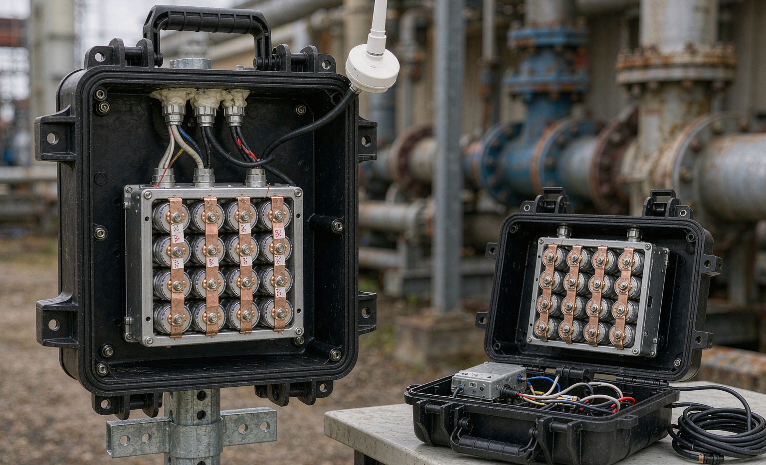
What Deployment Actually Means for a Sensor Power Project
Teams treat deployment as “ship the boxes and bolt them on.” In practice, a sensor deployment is the period from dock exit to end-of-life replacement, and it contains at least five distinct engineering decisions: transport classification, site-specific derating, mechanical installation, commissioning and calibration, and fleet-level health monitoring. Skip any one of them and you will pay for it with truck rolls.
The economics are brutal. A single truck roll to a remote monitoring pole typically runs between 150 and 400 USD once you count labor, vehicle time and access permits. A network of 2,000 nodes does not need a high failure rate to destroy the business case: a 2% annual premature-replacement rate on a 2,000-node fleet is 40 unplanned visits per year, and that is before you count the data gaps your customer’s SLA charges you for. When we build a custom battery solution for a sensor customer, we design backwards from the truck-roll cost, not forwards from the datasheet.
Step 1: Site Survey and Load Profiling Before Anything Ships
The single most common deployment error I see is specifying the pack from a spreadsheet duty cycle rather than a measured one. A LoRaWAN soil-moisture node looks trivial on paper: sleep at 3 to 5 µA, wake every 15 minutes, transmit for about 40 to 60 ms at 20 dBm with peaks near 120 mA, then go back to sleep. Average current lands somewhere near 30 to 60 µA. Multiply by 8,760 hours and a 3.5 Ah 18650-based pack looks like it should run for a decade.
It will not, and the reasons are all site-specific:
- Temperature swings derate usable capacity. A pack rated at 25 °C can lose 10 to 20% of deliverable capacity at 0 °C and see calendar aging roughly double for every 10 °C rise above 25 °C. A pole-mounted enclosure in a desert climate can sit at 70 °C internal air temperature in summer.
- Retries are invisible in the spec. A node with a marginal RF link will re-transmit; three retries per message can add 30 to 50% to the energy budget and nobody models it.
- Sensor warm-up loads dominate. A gas sensor with a heated element or an optical turbidity probe with an LED source can draw 50 to 150 mA for several seconds per sample — hundreds of times the sleep current.
- BMS quiescent current matters at microamp scale. A protection board with 25 µA quiescent draw doubles the sleep budget of an efficient node. I routinely specify sub-8 µA BMS solution front-ends for long-life sensor packs, with a load-detect wake circuit rather than a permanently active monitor.
My rule: instrument ten representative sites with data loggers for at least four weeks — ideally spanning a seasonal edge — and size the pack against the worst site, not the average. If the customer will not fund the survey, add 40% margin and say so in writing.
Step 2: Transport Classification, UN38.3 and the Paper Trail
Before a battery solution deployment for sensors can physically start, the packs have to get there legally. Every lithium cell and pack we ship has passed the UN38.3 test regime: T1 altitude simulation, T2 thermal cycling, T3 vibration, T4 shock, T5 external short circuit, T6 impact or crush, T7 overcharge and T8 forced discharge. Packs built with cells that also carry IEC 62133-2 certification cover the portable sealed-cell safety standard; industrial stationary configurations add IEC 62619, and anything racked in a fixed installation is designed to UL 1973.
Two logistics details cause the most delays:
- State of charge at shipment. Air freight of lithium-ion packs as UN3480 requires cells or packs at no more than 30% state of charge, with the packing instruction and the shipper’s declaration matching. Sea freight is more forgiving on SoC but slower, and for a rollout with a fixed installation window, air is usually the only option.
- Watt-hour classification. Packs above 100 Wh move into a different handling class with additional labeling and quantity limits. Sensor packs are usually well under this — a 7.4 V / 20 Wh pack is typical — but multi-node gateway batteries with 12 V / 40 Ah configurations land at 480 Wh and change the shipping paperwork entirely.
Get the test summary, the safety data sheet and the shipper’s declaration into one document packet per SKU, and hand it to the logistics team before the purchase order closes. I have seen a 6,000-node rollout sit in a bonded warehouse for eleven days over a missing test summary. The same discipline applies to every drone battery pack we ship for the inspection UAVs that survey these networks — one missing document grounds the aircraft just as effectively as it strands the sensors.
Step 3: Mechanical Installation That Decides Field Life
Here is where field life is won or lost. The cell chemistry gets the press coverage; the enclosure gets the warranty claims.
Enclosure rating and thermal reality
IP66 or IP67 per IEC 60529 is the baseline for pole-mounted sensor enclosures, and IK08 per IEC 62262 is a sensible impact target for anything within reach of a vehicle or a curious public. But a fully sealed IP67 box in a humid climate is also a condensation chamber. My standard practice is a sealed enclosure plus a hydrophobic breather vent (ePTFE membrane) so pressure equalizes without pulling liquid water in, plus a desiccant pack sized for the internal free volume and a service note to replace it at every maintenance visit.
Thermally, I ask for three things: a radiation shield or reflective finish on any enclosure in direct sun, an air gap between the pack and the enclosure wall, and — on hot-climate deployments — a shaded north-face or ground-level mount instead of a sun-facing pole. Moving a pack from 65 °C to 45 °C internal temperature can double its calendar life. That is worth more than any chemistry upgrade.
Mounting, strain relief and vibration
Sensor nodes on bridges, rail corridors, mining conveyors and agricultural machinery see continuous vibration. We build to IEC 60068-2-6 sinusoidal vibration and IEC 60068-2-27 mechanical shock as a minimum, and we validate the pack’s internal construction — not just the cell — because a spot-welded nickel tab with insufficient weld energy will crack long before the cell fails. Every cable exit gets a properly torqued M12 or M16 gland with a documented torque value, and every internal harness gets strain relief so that vibration load never reaches a solder joint.
Hazardous areas
For oil and gas, wastewater or grain-handling deployments, the enclosure has to satisfy the area classification — typically Zone 2 / Division 2, with encapsulated or potted battery packs and no user-serviceable cell access. This constrains the pack design up front: you cannot retrofit a field-replaceable pack into an Ex-certified enclosure. Decide this during battery pack design, not at installation.
Step 4: Commissioning — BMS Configuration, SoC Calibration and Baseline Logging
The most under-rated day in a deployment is commissioning. Two hours per site spent here prevents two years of ambiguous failure data.
- Set protection thresholds for the site, not the cell. Low-temperature charge cutoff is non-negotiable: charging a standard graphite-anode lithium-ion cell below 0 °C plates lithium metal and permanently removes capacity while creating a safety risk. If the deployment includes any energy harvesting or solar trickle charging, the BMS solution must gate charge on cell temperature, not ambient temperature.
- Record a real baseline. Measure and log pack DC internal resistance and open-circuit voltage at install, along with the site’s GPS, mounting orientation and enclosure type. Twelve months later, a resistance rise of 25 to 30% over baseline is your earliest reliable end-of-life signal — far earlier than capacity fade shows up in runtime.
- Calibrate the state-of-charge gauge on site. Coulomb counting drifts. A pack installed at partial charge and never taken through a full relaxation cycle will report SoC errors of 10 to 20% within months, and your analytics team will chase phantom failures. For long-life sensor nodes I usually disable the coulomb counter display entirely and report voltage-plus-temperature-derived state of health instead. It is less pretty and far more honest.
Step 5: Remote Monitoring, Fleet Analytics and Replacement Triggers
A deployed sensor battery fleet is a data product. At minimum, have each node report pack voltage under load, cell temperature, cumulative charge throughput if rechargeable, and a count of under-voltage events. Then build the analytics around cohorts, not individual nodes: group by installation quarter, enclosure type and climate zone, and watch the cohort’s voltage-under-load distribution.
The replacement trigger I recommend is a combination condition: state of health below 80% of nameplate capacity or DC resistance more than 30% above the commissioned baseline or any cell group diverging more than 100 mV from its neighbors under load. The third condition catches the failure mode that actually strands trucks — a single weak parallel group dragging the pack into under-voltage shutdown while the rest of the pack still has 70% capacity left.
Plan the replacement wave deliberately. Batteries deployed in the same month fail in the same month, so stagger either the chemistry margin or the installation schedule, and pre-position spares at roughly 3% of fleet size with a second order at 5% once the first cohort hits year four.
Where Semi-Solid and Sodium-Ion Cells Fit a Deployment Plan
The chemistry choice is a deployment decision, not just a cell-data-sheet decision. Three options dominate the conversations I have:
- Conventional lithium-ion (NMC or LFP). The default for a reason: mature supply, 2,000 to 6,000 cycles for LFP, well-understood transport classification, and a wide range of certified form factors. For most sensor networks, a lithium battery pack built on LFP with a low-quiescent BMS is still the lowest-risk answer.
- Semi-solid-state cells. Higher energy density in the same envelope and better abuse tolerance, which helps when you are volume-constrained inside a small pole enclosure or shipping to a customer with strict safety documentation. The trade-off is cost per Wh and a narrower supplier base — fine for a 500-node premium deployment, harder for 50,000 nodes.
- Sodium-ion cells. The interesting one for stationary sensor infrastructure. Cold-temperature charge acceptance is better than lithium-ion, which removes the low-temperature charge-gating complexity in northern deployments, and the raw material base is more stable in price. Energy density is lower, so a sodium-ion battery pack is physically larger for the same watt-hours — often acceptable for a ground cabinet, rarely acceptable for a small pole box.
I also get asked about home energy storage topology for sensor gateways. When a gateway site already has a solar array and a small storage bank, powering the sensor network from that bank through a dedicated DC-DC feed is usually cleaner than giving each node its own primary cell — but only if the bank’s BMS is configured to reserve capacity for the sensor load. I have seen a gateway shed its entire telemetry network during a five-day cloudy stretch because load shedding prioritized the wrong circuit.
Cost, Warranty and Total Cost of Ownership
Procurement teams compare dollars per amp-hour. Deployment teams should compare dollars per site-year. A pack that costs 40% more and eliminates one truck roll over a ten-year life is cheaper, and the maths usually works out by year four.
When I review a warranty for a battery application solution, I read three clauses: the capacity-retention guarantee and the test conditions behind it (a 70% retention claim at 25 °C means something different at 45 °C), whether the warranty covers removal-and-replacement labor or only the part, and whether field data from the node’s own BMS is admissible as warranty evidence. That last one saves weeks of argument.
Frequently Asked Questions
How long should a lithium battery pack last in a wireless sensor node?
For a well-designed LoRaWAN or NB-IoT node with a low-quiescent BMS and a pack sized to the worst-case site, plan for 5 to 10 years on primary lithium cells and 3 to 7 years (or 2,000 to 4,000 equivalent cycles) on rechargeable LFP with harvesting. The dominant variable is temperature, not cycle count — most field failures I investigate are calendar aging accelerated by heat.
What certifications should I require before a sensor battery deployment?
UN38.3 test summary for transport, IEC 62133-2 for the cells and packs in portable service, IEC 62619 for industrial stationary equipment, and UL 1973 where packs are racked in a fixed installation. Add IEC 60068-2-6 and IEC 60068-2-27 evidence if the site has vibration, IEC 60529 ingress ratings for the enclosure, and ATEX or IECEx documentation for hazardous areas.
Can I fly sensor battery packs to the deployment site?
Yes, but plan for it. Packs must be at 30% state of charge or less for air freight as UN3480, the shipper’s declaration and labeling must match the packing instruction, and packs above 100 Wh move into stricter handling. I tell customers to add three weeks to the schedule for lithium freight documentation on any international rollout.
Should I choose sodium-ion or lithium for cold-climate sensor sites?
If the site regularly sees sub-zero temperatures and the pack will be charged in place, sodium-ion removes the low-temperature charge-gating complexity and performs better on cold charge acceptance. If the enclosure is small and volume-constrained, LFP still wins on energy density. For unheated cabinets in northern latitudes, I lean sodium-ion; for compact pole-mounted boxes, I stay with lithium.
How do I know when a deployed sensor battery needs replacing?
Watch three signals, not one: state of health below 80%, DC internal resistance 30% above the commissioned baseline, and cell-group divergence above 100 mV under load. Log all three at commissioning so you have a baseline to compare against — without it, you are guessing and paying for truck rolls to find out.
What is the biggest mistake in battery solution deployment for sensors?
Sizing the pack from a spreadsheet duty cycle instead of a measured one, then installing without a baseline resistance and voltage log. Those two shortcuts are behind most of the “the batteries failed early” calls I take. In the majority of cases the cells performed exactly as designed — the deployment simply asked them to do a job nobody had measured.
Every network we power — from a 40-node greenhouse monitoring trial to an industrial telemetry fleet measured in thousands — goes through the same five stages. It is slower at the start and dramatically cheaper by year three. If you are planning a battery solution deployment for sensors and want a second opinion on the load profile, the enclosure thermal design or the freight classification, that review is worth doing before the purchase order, not after the first truck roll.





