
Battery Solution Reliability for Equipment
Every quotation request I receive for industrial machinery starts with the same three numbers: voltage, capacity, and price. Almost nobody opens with the number that actually decides whether the project succeeds — the acceptable field failure rate over eight years of duty. I have spent the last eleven years designing and qualifying packs at Horizon Power, and I can tell you plainly that battery solution reliability equipment programs fail far more often from unexamined duty cycles and sloppy mechanical detailing than from bad cells. The cells are usually the best-characterised component in the whole assembly.
This guide is the internal checklist my team uses when a customer brings us a floor scrubber, an AGV, a mobile compressor, a rail inspection trolley, or a portable diagnostic cart and asks for a custom battery solution that will not come back. I have kept the numbers as they appear in our test reports, including the ones that are less flattering than a datasheet.
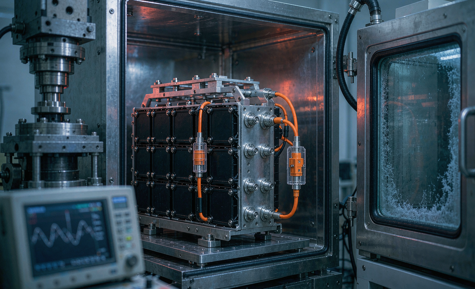
What Reliability Actually Means in an Equipment Battery Solution
Reliability is not a single figure of merit. When we write a specification, we break it into four measurable commitments, because each one is verified by a different test and defended by a different design decision.
- Capacity retention: usable energy remaining after a defined cycle and calendar life. Our standard industrial commitment is ≥80% of nameplate at 3,000 cycles for LFP chemistry at 80% depth of discharge, 25 °C ±5 °C.
- Power retention: DC internal resistance growth. A pack that still holds 82% capacity but has gained 60% DCIR will trip undervoltage protection under motor inrush and the operator will call it dead. We cap allowable DCIR growth at 35% over the same window.
- Availability: the fraction of scheduled shifts the machine actually runs. This is where connector wear, charger handshake faults, and BMS lockouts dominate — not cell ageing.
- Safety margin: no thermal propagation beyond the initiating cell, verified physically rather than argued on paper.
Splitting the target this way changes engineering behaviour. A lithium battery pack designed only against a cycle-life number will be built with the cheapest interconnects that pass initial resistance checks. A pack designed against all four will get four-wire-verified welds and a serviceable connector, because two of the four commitments depend on them.
The Duty Cycle Audit Comes Before Any Cell Selection
I refuse to quote a serious industrial project from a nameplate alone. We instrument the customer’s existing machine — usually with a lead-acid pack still fitted — and log current, voltage, and ambient temperature at 10 Hz for a minimum of two full working weeks. The data almost always contradicts the written specification.
A concrete example from a warehouse floor-scrubber programme last year. The customer specified “24 V, 100 Ah, 30 A average draw.” What we logged over 14 days:
- Mean discharge current: 26 A — close to the claim.
- Brush-engagement and traction inrush peaks: 140–165 A for 300–800 ms, occurring roughly 90 times per shift.
- Regenerative braking pulses: 20–35 A charge current, up to 400 events per shift.
- Actual daily energy throughput: 61% DOD, not the 80% assumed.
- Ambient inside the battery bay: 41–47 °C during summer afternoon shifts, 16 °C above room temperature, because the bay sat next to the vacuum motor.
Three of those five findings changed the design. The 165 A peak set the busbar cross-section and the continuous-current rating of the contactor. The 400 daily regen pulses meant charge-direction current handling had to be sized properly rather than treated as an afterthought. The 47 °C bay temperature was the decisive one: it moved the whole thermal calculation and, in the end, forced a vent redesign in the machine chassis. Had we skipped the audit, the pack would have aged at roughly 1.8× the modelled rate and the warranty reserve would have been consumed inside three years.
An accurate duty-cycle log is the cheapest reliability improvement available. It costs a data logger and two weeks of patience.
Cell Selection and Honest Derating for Industrial Duty
For equipment applications we default to LFP (LiFePO₄) unless volume or mass constraints genuinely forbid it. The reasoning is unglamorous and entirely reliability-driven: a flatter thermal-runaway risk profile, a decomposition onset around 250–270 °C versus roughly 200–215 °C for typical NMC, and a cycle-life curve that stays predictable at elevated temperature. Our qualified LFP prismatic cells deliver 5,800–6,400 cycles to 80% capacity at 80% DOD and 25 °C in our own long-term racks; the same cells at a 40 °C average return 3,100–3,600 cycles. That temperature sensitivity is exactly why the duty-cycle audit matters.
Where energy density is non-negotiable — handheld instruments, mobile robots with tight bays — we move to high-nickel NMC or a semi-solid state battery cell and accept a shorter cycle life (1,800–2,600 cycles) in exchange for 240–290 Wh/kg at pack level. The engineering discipline then shifts toward thermal management and tighter voltage-window control.
Our derating rules, applied without negotiation:
- Continuous current limited to 70% of the cell’s datasheet continuous rating.
- Pulse current limited to 80% of the datasheet pulse figure, with pulse duration verified against the manufacturer’s stated test window rather than assumed.
- Charge voltage set 30–50 mV below the maximum. On LFP we charge to 3.60 V rather than 3.65 V; this alone has added 12–18% to cycle life in our comparative racks.
- No charging below 0 °C without active heating. Plating at low temperature is the single most common cause of premature failure I see in returned third-party packs.
- Usable window capped at 90% of theoretical, so the operator never sees the knee of the curve.
Those five rules cost roughly 8–12% of nameplate energy. They routinely double field life.
Mechanical Design: Vibration, Shock, and Ingress Decide the Warranty
Analysing our warranty returns across 2023–2025, mechanical and electrical-connection faults accounted for 68% of confirmed pack failures in equipment applications. Cell-level degradation accounted for 19%. The remaining 13% were charger or vehicle-side issues misattributed to the pack. Read that ratio again — it is the reason my team spends more design hours on fixturing than on cell modelling.
What we do about it:
- Cell restraint: prismatic cells compressed between end plates at 0.3–0.5 MPa face pressure using compressible foam pads, so expansion over life is accommodated without losing preload. Loose cells chafe, and chafed cells eventually vent.
- Interconnects: laser-welded nickel or aluminium busbars in preference to threaded terminals wherever serviceability allows. Where bolted joints are unavoidable, we torque to 8–10 N·m with a calibrated wrench, mark the joint, and re-verify at first service.
- Joint verification: every weld and joint measured with a four-wire micro-ohmmeter. Acceptance threshold is <0.15 mΩ, and any joint above 0.10 mΩ is flagged for review. A single 0.5 mΩ joint carrying 150 A dissipates 11 W into a spot the size of a fingernail.
- Wire management: sense wires routed with strain relief and a service loop, never tensioned across a cell face. Broken sense leads generate phantom faults that consume more service labour than any real defect.
- Ingress: IP65 minimum for indoor equipment, IP67 for anything that meets a wash-down or outdoor cycle, tested per IEC 60529 with pressure-equalisation membranes fitted rather than sealed-and-hoped.
Vibration qualification follows IEC 60068-2-6 for sinusoidal sweeps and IEC 60068-2-64 for random profiles, with the PSD derived from our own machine-mounted accelerometer logs rather than a generic table. Mechanical shock follows IEC 60068-2-27. For road-going or trailer-mounted equipment we additionally apply ISO 16750-3 profiles. When a customer’s machine is genuinely severe — tracked or off-road — we escalate to MIL-STD-810H Method 514.8 category 4 or 20, which is far harsher than most commercial batteries ever see.
BMS Architecture and Fault Tolerance
The BMS is where reliability is either engineered or merely claimed. Our specification for equipment packs:
- Dual-layer protection: primary MCU-based protection plus an independent secondary hardware comparator chain that opens the contactor even if the firmware hangs. This is not optional at industrial voltage and energy levels.
- Voltage sensing: ±5 mV accuracy across the operating temperature band. Balance thresholds set at 20 mV, with passive balancing sized for 80–150 mA — enough to hold a well-matched pack, since chasing large imbalance with a resistor bank is a symptom of poor cell grading, not a solution.
- Temperature sensing: minimum one NTC per four cells, plus dedicated sensors on the busbar and both contactor terminals. Terminal sensors have caught more incipient problems in our fleet than any cell sensor.
- Fail-safe behaviour: defined and documented degraded modes. A single lost temperature sensor should derate current to 50%, not shut the machine down mid-shift and not ignore the fault either.
- Diagnostics: CAN bus with a documented DBC file, event logging with time stamps, and retrievable fault history. When a pack does come back, a log turns a three-day investigation into a twenty-minute one.
- Functional safety alignment: where the host machine is assessed under IEC 61508 or ISO 13849, the battery disconnect path is documented as part of the safety function rather than bolted on afterwards.
One field observation worth passing on: roughly 30% of “BMS failures” reported to us over the past two years were actually communication timeouts caused by vehicle-side CAN termination problems. Specify termination and shielding explicitly in the interface document, and insist on a signed interface control document before build.
The Qualification Test Plan We Actually Run
Regulatory compliance and reliability qualification are different exercises with different objectives. We run both, in this order.
Mandatory transport and safety compliance:
- UN38.3 tests T.1 through T.8 — altitude simulation, thermal cycling, vibration, shock, external short circuit, impact/crush, overcharge, and forced discharge. Non-negotiable for shipment, and we retest after any change to cell supplier, enclosure, or interconnect method.
- IEC 62133-2 for portable sealed lithium cells and batteries, applicable to smaller instrument and handheld packs.
- IEC 62619 for industrial secondary lithium batteries, which is the correct standard for most stationary and mobile equipment packs, including its propagation and functional-safety requirements.
- IEC 62620 where the application is classified as industrial traction.
Reliability qualification beyond compliance:
- Accelerated cycle life at 25 °C, 40 °C, and 55 °C to build an Arrhenius model rather than extrapolate a single curve. We run a minimum of 500 cycles at each point before releasing a life prediction.
- Calendar ageing at 45 °C and 100%, 50%, and 30% state of charge, measured at 30-day intervals.
- Thermal cycling from −20 °C to +60 °C, 200 cycles, with joint resistance re-measured before and after. This test finds bad welds that vibration alone misses.
- Single-cell thermal propagation trial per IEC 62619, nail penetration or heater initiation, with the pass criterion that no adjacent cell exceeds 150 °C and no external flame is observed.
- Connector durability: 5,000 mate/de-mate cycles with contact resistance monitored throughout. On daily-swap equipment this is the highest-value test in the entire plan.
- Ingress retest after the mechanical sequence, because a pack that was IP67 before vibration is not automatically IP67 afterwards.
A full qualification programme for a new equipment platform takes 14–18 weeks. Cycle life cannot be rushed, though we do run the mechanical, ingress, and propagation sequences in parallel to save four to five weeks.
Field Reliability Data From Deployed Fleets
Design intent means little without returns data. Across roughly 12,400 industrial equipment packs shipped between 2021 and 2025, and tracked through our service records:
- Confirmed field failure rate at 24 months: 0.47%.
- Failure rate at 48 months: 1.9%, dominated by connector wear on daily-swap machines.
- Mean capacity retention at 1,500 cycles across returned-and-measured LFP packs: 91.3%.
- Mean DCIR growth at 1,500 cycles: 14.8%, comfortably inside the 35% ceiling.
- Warranty-return root causes: 41% connector or cable, 27% mechanical/fixturing, 19% cell degradation, 13% host-machine or charger interaction.
- Zero thermal events resulting in propagation beyond the initiating cell.
The pattern has been stable for four years and it drives our design priorities. When someone asks me where to spend an extra ten dollars per pack, I do not say better cells. I say a better connector and a better clamping system, every time. The same lesson carried over from our drone battery work, where connector and lead-wire integrity under vibration proved more decisive than cell grade — an aviation-adjacent discipline where FAA and EASA guidance on lithium battery carriage keeps everyone honest.
Frequently Asked Questions
How long should a well-designed equipment battery solution last?
For LFP-based packs running one shift per day at 60–80% DOD in a controlled indoor environment, 8–10 years is a realistic service life, corresponding to 2,500–3,000 cycles at ≥80% retention. Add heat and the number falls quickly: at a 40 °C average pack temperature, plan for 5–6 years. Multi-shift operation at 90% DOD with fast charging typically lands at 4–5 years. Any supplier quoting a single life figure without asking about ambient temperature and depth of discharge has not done the analysis.
Is LFP always the right chemistry for industrial equipment?
Not always, but it is the correct default. LFP wins on cycle life, thermal stability, and cost per delivered kilowatt-hour. It loses on volumetric and gravimetric energy density, roughly 150–175 Wh/kg at pack level against 240–290 Wh/kg for high-nickel NMC or semi-solid state cells. If the machine has a fixed bay that cannot be enlarged and the shift requirement will not fit in LFP, we move chemistry and compensate with tighter thermal control and a more conservative voltage window.
What does the qualification programme cost, and can we skip parts of it?
For a new industrial platform, expect a five-figure figure in USD for the full sequence, with UN38.3 and IEC 62619 accounting for a substantial share. You cannot skip UN38.3 if the pack will be shipped, and you should not skip the propagation trial. What can reasonably be trimmed on a derivative design — same cells, same interconnect method, modified enclosure — is the accelerated cycle-life work, provided the original data set is transferable and documented as such.
How do I compare quotations from different suppliers fairly?
Ask every bidder for four specific items: the derating factors applied against the cell datasheet, the four-wire joint resistance acceptance limit, the vibration profile used for qualification and its source, and the measured field return rate at 24 months on comparable products. A supplier who can answer all four has an engineering organisation behind the quotation. A supplier who answers only on price and lead time is selling you an assembly, not a custom battery solution.
What information should I bring to the first design meeting?
Bring a current-versus-time log from the actual machine if at all possible, even a rough one from a clamp meter and a laptop. Then bring the bay dimensions with tolerances, the mounting interface, the measured ambient temperature range inside the bay, the charging infrastructure and available charge window, the shift pattern, and the target service life. With those seven items we can produce a defensible concept in about a week. Without the current log, everything that follows is an assumption dressed up as a specification.
Closing Thoughts From the Test Floor
The most reliable equipment packs I have shipped were not the ones with the most advanced cells. They were the ones where we logged a real machine before drawing anything, applied derating without arguing, verified every joint, and ran the full qualification sequence even when the schedule hurt. None of that is exotic — and all of it is skippable, which is precisely why so many programmes skip it and discover the cost in year three.
Karl Huang is a Senior Lithium Battery Engineer at Horizon Power, specialising in custom battery solution design and qualification for industrial equipment, robotics, and unmanned aerial platforms.





