
Battery Solution Safety for Robotics
I have spent the last eleven years designing lithium battery packs for industrial equipment, and the robotics programmes are the ones that keep me up at night. Not because the cells are exotic — most warehouse robots run the same 21700 cylindrical or prismatic LFP cells found in dozens of other applications — but because a mobile robot puts a high-energy pack inside a machine that moves autonomously around people, docks itself to a charger unattended, and absorbs forklift traffic for eight years. battery solution safety for robotics is therefore not a cell datasheet question. Every custom battery solution we ship into a robotics fleet has to survive that reality, so safety becomes a systems discipline spanning hazard analysis, layered electrical protection, propagation containment, and functional safety integration with the robot controller. Here is how my team actually builds that chain of evidence.
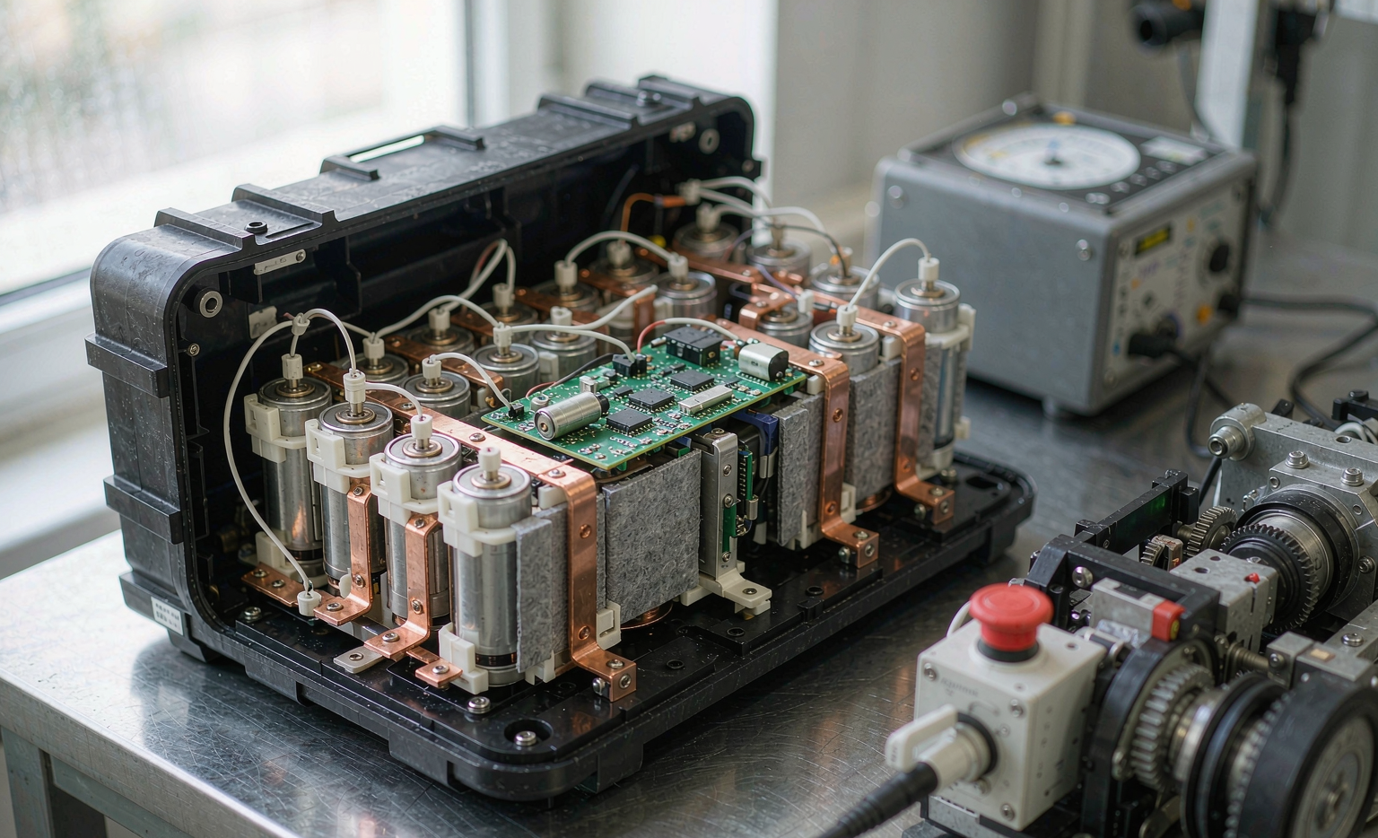
Why Robot Battery Safety Is a System Problem, Not a Cell Problem
When a specification arrives saying “must be UN38.3 certified and IEC 62619 compliant,” I know the real safety work has not started. Those certificates prove a defined construction survives a defined set of abuse tests. They say nothing about what happens when the traction inverter latches a 300 A fault, or when a pallet corner deforms the housing in month fourteen.
Safety lives at four boundaries, each with its own standard family: the cell, the pack, the machine, and the site. IEC 62619 governs the industrial pack. ISO 3691-4 governs driverless industrial trucks. Local fire code governs the charging room. Incidents cluster in the gaps between them — the pack supplier assumes the integrator handles emergency stop behaviour, while the integrator assumes the pack “protects itself.” A credible battery solution closes that gap in writing, with an interface specification that states exactly which party owns which protective function.
Hazard Analysis Before Cell Selection
We run a HAZOP-style review and a design FMEA before quoting a chemistry. The output is a quantified hazard list, not adjectives. For a typical 13S4P robot pack we document: prospective external short current of 1,500–1,800 A across the terminals given roughly 30 mΩ pack resistance; repeated 90–130 A stall pulses lasting about two seconds when a drive wheel jams; crush loads from forklift contact; water ingress during floor wash-down; and sub-zero charging in cold-store aisles.
Chemistry then follows from the hazard list. LFP begins thermal runaway around 200–250°C and peaks near 300–500°C. NMC begins around 150–180°C and can peak at 600–800°C. LFP costs roughly 30–40% in energy density but makes containment dramatically simpler. Where a robot has volume to spare, LFP is a safety-driven choice. In a drone battery, where every gram is contested, we accept NMC and spend the safety budget on barriers and redundant protection instead. Those trade-offs are exactly what a custom battery solution exists to resolve.
Layered Electrical Protection: Independence Is Non-Negotiable
Protection must be layered, and the layers must be genuinely independent. Our standard architecture for a robot lithium battery uses four.
- Firmware thresholds in the BMS: overvoltage 4.25 V ±25 mV, undervoltage 2.80 V with 200 ms debounce, overcurrent 120 A, over-temperature warning at 60°C and cut-off at 70°C.
- Independent hardware secondary protection: a separate protection IC on different silicon, with its own voltage reference and its own cell sense taps, latching at 4.35 V. A firmware defect or an MCU lock-up cannot disable it.
- Non-resettable protection: a 150 A fast-acting fuse with a 10 kA interrupt rating, sized below both busbar and cell-tab ampacity so the fuse always clears first.
- Thermal cut-off: a PTC or one-shot thermal fuse independent of all electronics.
The governing rule: no two layers may share a sense line, a voltage reference, or a power rail. We prove independence by fault injection rather than by assertion — cutting the sample harness, shorting and open-circuiting the NTC, welding the MOSFET closed, and dropping firmware power mid-update. Each injection has a documented expected response and a captured log.
Containing Thermal Runaway Propagation
Single-cell failure is a statistical certainty across a fleet. The engineering objective is that one cell failing never becomes fifty-two cells failing. IEC 62619 and the UL 9540A methodology both trigger a single cell — by nail penetration or a dedicated heater — and require no propagation to adjacent cells and no flame outside the enclosure, which maps to EUCAR hazard level 4 or below.
What actually achieves that in a robotics battery solution is unglamorous: 0.3–0.5 mm mica sheet between cell rows, 1–2 mm aerogel in the worst-case gaps, 2–3 mm cell spacing to break the conduction path, and busbar geometry that avoids turning copper into a heat pipe into the next block.
Venting is the part most designs get wrong. A single 21700 in runaway releases roughly 30–50 L of gas, so a sealed enclosure is not an option. We design a deliberate relief area that opens at 15–25 kPa, oriented away from the operator position and away from the robot’s electronics bay. Without a designed vent path, gas escapes at whichever seam is weakest — frequently the one beside the BMS, destroying the diagnostic record we need afterwards.
Functional Safety Integration With the Robot
ISO 3691-4 applies to driverless industrial trucks, and ISO 10218-1/-2 with ISO/TS 15066 applies to collaborative arms. These standards require safety functions to carry a rating, typically Performance Level d, Category 3 under ISO 13849-1 — single-fault tolerance plus diagnostics — broadly equivalent to SIL 2 under IEC 61508.
The battery participates directly. Emergency stop must open the main contactor, but the BMS must remain powered so it continues monitoring temperature and logging. Defining that safe state is the key deliverable: contactor open, BMS alive, CAN heartbeat maintained, and no automatic reclosure without deliberate operator action.
To reach diagnostic coverage of 90–99% we measure pack current twice, from a shunt and a Hall device, and continuously compare the sum of cell voltages against the measured pack voltage. A mismatch beyond 150 mV flags a broken sense line within a single sampling cycle. The CAN heartbeat runs at 100 ms with a 300 ms timeout, and a timeout triggers a controlled derate rather than an abrupt trip that would strand a loaded robot in an aisle.
Charging and Docking: Where Field Incidents Actually Start
Reviewing our own field returns across every robotics battery solution we support, the charge interface dominates. Robots charge unattended 15–20 times per day, and nobody is watching.
Docking contacts begin around 2 mΩ. After 12,000–15,000 insertion cycles we routinely measure 15–25 mΩ. At 35 A that dissipates 18–30 W inside a connector rated for a fraction of it, producing local temperatures of 90–120°C and, eventually, melted housings. Our countermeasures are silver-plated or gold-flashed contacts, contact-resistance monitoring in the BMS that alarms when the charger-to-pack voltage delta exceeds 250 mV at 30 A, and a pilot pin that breaks first so current commutates before mechanical separation.
Temperature gating is absolute. No charge below 0°C, ever. Charging cold cells plates metallic lithium instead of intercalating it, and plated lithium seeds dendrites that can pierce the separator months later. For cold-store fleets operating at −5 to 5°C we fit a 60–80 W heater and hold charging until cells reach 5°C. The operating envelope we specify is 0–45°C charge, −20 to 60°C discharge, with a proper constant-voltage taper and no float charge.
Ingress, Mechanical Protection, and Electrical Isolation
We qualify to IP65 per IEC 60529, and we run that test after vibration and shock rather than before — sealing that passes on a virgin sample frequently fails once gaskets have been worked. Vibration follows SAE J2380 and ISO 12405 profiles at approximately 0.04 g²/Hz for eight hours per axis, with mechanical shock per IEC 60068-2-27.
A 48 V nominal pack sits below the 60 V DC decisive-voltage threshold, so electric shock risk is low, but short-circuit energy is not. That 1,500 A prospective current will vaporise a dropped screwdriver, so we mandate terminal covers, insulated tooling, and a service disconnect. We still require at least 1 MΩ insulation resistance from pack to housing and hipot at 500 V DC to catch pinched harnesses. On 60 V-class systems and above we add ground-fault detection. Crush protection comes from a load-bearing 2–3 mm steel or 5 mm aluminium shell, never from the plastic cosmetic cover.
Certification and Transport Compliance
UN38.3 tests T.1 through T.8 cover altitude simulation, thermal cycling, vibration, shock, external short circuit, impact or crush, overcharge, and forced discharge. Since 2020 the test summary must be made available on request, so ask for it — and check that it corresponds to the exact construction being shipped, not a cousin of it.
Beyond that, IEC 62619 covers industrial cells and batteries including propagation, IEC 62133-2 covers smaller sealed packs, UL 2580 appears where the customer’s market demands it, and UL 9540A becomes relevant when the local authority having jurisdiction asks about fire behaviour in the charging room. For transport, IATA PI965 requires air shipment at 30% state of charge or below; ground movement follows ADR or DOT rules with UN-rated packaging.
The caveat that catches buyers: certification is construction-specific. Changing the cell supplier, the barrier material, or the BMS safety logic invalidates it. We hold a formal change-control gate that names re-qualification triggers explicitly.
Field Safety: Damaged Packs, Storage, and Operator Protocol
Documentation is part of the product. Every pack ships with a written protocol covering the situations that actually arise.
- Damaged, swollen, or dropped packs: do not charge, do not ship by air, quarantine at least one metre from combustibles in a non-combustible container, reduce to roughly 30% state of charge if it can be done safely, and observe for 24 hours.
- Storage: 30–50% state of charge, 15–25°C, 35–55% relative humidity, first-in-first-out rotation, open-circuit voltage rechecked every six months and full retest beyond twelve months.
- Handling: insulated tools, no metal jewellery, terminal covers fitted before any transport within the facility.
- Site response: lithium pack fires need copious water for cooling, not CO₂. Give the fire marshal the chemistry and the energy content in advance — a 13S4P 21700 pack is roughly 2.4 kWh.
- Retirement: remove from service at 70–80% state of health, and do not cascade industrial packs into unmanaged second-life use.
The Safety Evidence Package We Deliver
Safety claims are only as good as the documents behind them. With every robotics programme we hand over eight items: the hazard analysis and design FMEA with mitigations traced to specific test reports; the UN38.3 test summary matched to the exact bill-of-materials revision; IEC 62619 or IEC 62133-2 reports including propagation results; a protection independence matrix with the full fault-injection log; the safe-state and emergency-stop interface specification with its ISO 13849-1 Performance Level justification; ingress and vibration reports that show the test sequence order; the change-control register naming re-qualification triggers; and the field handling, storage, transport, and emergency response documents.
If a supplier cannot produce the independence matrix, the safe-state interface specification, and the change-control register, they are selling cells in a box. The difference between an assembled pack and an engineered, documented battery solution is the difference between a fleet that runs safely for eight years and one that has an incident in year two.
Frequently Asked Questions
Does a UN38.3 certificate mean my robot battery is safe?
No. UN38.3 qualifies a pack for transport against defined abuse tests. It says nothing about propagation containment, protection-layer independence, charging safety, or emergency-stop integration. Treat it as a shipping prerequisite, not a safety case. Also request IEC 62619 results, fault-injection records, and the safe-state interface specification for your robot controller.
Should I choose LFP or NMC cells for a mobile robot?
For most warehouse robots, LFP. Runaway onset sits near 200–250°C versus 150–180°C for NMC, and peak temperatures are far lower, so containment becomes simpler and cheaper. Choose NMC only when mass or volume is genuinely constrained, and then budget for thicker barriers and fully redundant protection layers.
Why can a pack never be charged below 0°C?
Charging cold cells plates metallic lithium rather than intercalating it. That plated lithium seeds dendrites capable of piercing the separator months later, producing an internal short with no external warning beforehand. We gate charging until cells reach 5°C, adding a 60–80 W heater for cold-store fleets.
What does ISO 13849-1 Performance Level d require from the battery?
It requires battery safety functions — contactor opening on emergency stop, overcurrent cut-off — to tolerate a single fault and detect faults with high diagnostic coverage. In practice that means redundant current sensing, cross-checked voltage measurement, and a defined safe state where the contactor opens while the BMS stays powered and logging.
How often should robot batteries be inspected?
Quarterly visual and connector inspection, supported by continuous BMS telemetry review. We flag docking-contact voltage drop above 250 mV at 30 A, cell imbalance above 60 mV after balancing, and capacity-fade trends. Physical inspection matters most at the charge interface, where the majority of field faults originate.





