
Battery Solution Testing for Sensors
Why Sensor Batteries Demand a Different Test Philosophy
When a logistics customer asked me to qualify a battery solution for 4,000 wireless temperature sensors scattered across a cold-chain network, the first thing I told them was this: do not reuse the test plan you would use for an e-bike or a power tool. A sensor battery lives a strange life. It spends 99.9% of its time asleep at microamp draw, wakes for a few milliseconds to transmit, and may not be touched again for five to fifteen years. The failure modes that matter for a high-rate pack — thermal runaway under load, voltage sag at 30 A — are almost irrelevant here. What kills a sensor battery is self-discharge drift, a noisy protection circuit that silently bleeds charge, a weld joint that corrodes in humid air, or a cell that passes incoming inspection but fades 4% a year instead of 1%.
Over eighteen years building custom battery solution programs at Horizon Power, I have found that sensor packs are won or lost in the test lab, not on the spec sheet. A 2,000 mAh cell that self-discharges at 3% per year is a liability; a 1,800 mAh cell at 0.8% per year is the better part. You cannot see that difference with a multimeter on the production line — you have to measure it. This article walks through the validation protocol my team runs before any sensor lithium battery leaves the building.
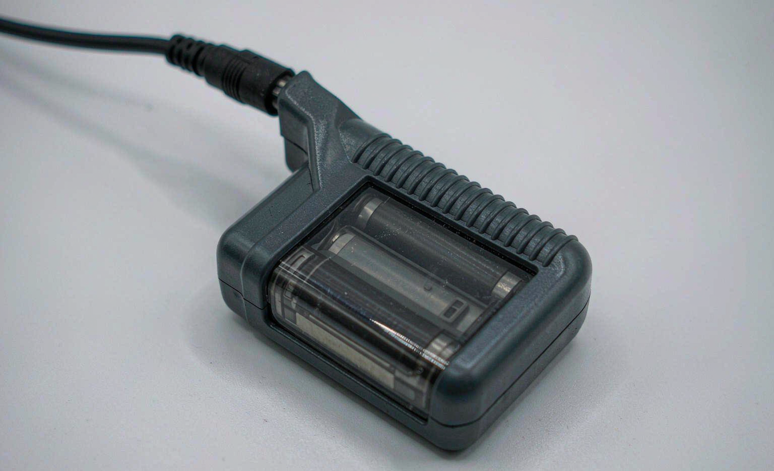
Step 1 — Incoming Cell Grading Beyond Capacity
Most factories grade cells on capacity alone. That is the first mistake. For a sensor pack, I grade on three independent axes, and I reject any lot that fails one:
- K-factor self-discharge. I store samples at 45°C for 7 days after a full charge and measure open-circuit-voltage drop. Any cell losing more than 1.0 mV/day equivalent is rejected. In one batch of Li-SOCl2 primaries, 6% of cells measured a K-factor above the gate and would have stranded sensors inside two years instead of ten.
- 4-wire Kelvin internal resistance (DCIR). I measure at 1 kHz and at DC with a dedicated Kelvin fixture, rejecting cells outside ±10% of the lot median. Even though the sensor draw is tiny, a high-DCIR cell ages faster and shows larger cold-temperature voltage collapse.
- Capacity and AC impedance correlation. I bin cells into ±3% capacity groups and pair them within a pack so that no two cells differ by more than 6% capacity or 15% impedance. Mismatched cells are the hidden cause of premature end-of-life in series sensor strings.
Every accepted cell gets a DataMatrix code laser-marked before assembly. That genealogy travels with the finished battery solution for its entire service life — when a field unit fails, I can trace it to the exact cell lot and test record.
Step 2 — Pulsed Functional Test, Not a Steady Drain
The classic “constant 1 mA until cutoff” discharge test is misleading for sensors because it never exercises the real duty cycle. A wireless sensor typically sleeps at 2–15 µA, spikes to 80–180 mA for 5–50 ms during a radio transmit, then returns to sleep. I replay that exact current trace on a programmable load and watch three things:
- Quiescent draw of the protection/BMS section. A poorly designed lithium battery management section can sit at 5 µA; a careless one sits at 25 µA and silently halves the service life. I measure the whole-pack sleep current and reject anything above 5 µA.
- Voltage dip at transmit. Under the pulse, the pack voltage must stay above the radio’s brownout threshold with margin. I gate any pack that sags more than 8% below the transmit floor.
- Wake recovery. After 1,000 simulated transmit cycles, I re-measure sleep current. A protection MOSFET with a leak path will show a creeping quiescent rise — exactly the failure that defeats a “10-year” primary cell in three.
Step 3 — Environmental Stress and Seal Integrity
Sensor packs live outdoors, underground, or inside machinery. My environmental screen is built around the conditions I have actually seen kill units:
- Thermal cycling. −40°C to +85°C, 50 cycles, with a transmit pulse injected at each extreme. I verify the pack still meets its brownout gate at −40°C, where a marginal cell can collapse.
- Humidity and salt-mist. 85% relative humidity at 60°C for 240 hours, then salt-mist per IEC 60068-2-52. I open a sample teardown and inspect weld joints and the conformal coating for creep corrosion.
- Mechanical shock and vibration. I run MIL-STD-810H Method 516.8 (drop) and 514.8 (random vibration) and then repeat the pulsed functional test. A hairline weld crack that passes at rest will show up as a rising DCIR after vibration.
- Seal verification. For potted enclosures I do a helium-leak or dye-penetrant check on the cable entry and lid. A single capillary path is how moisture enters and slowly drains a sensor battery over a wet season.
Step 4 — Standards Floor and Transport Qualification
No sensor battery solution ships without clearing the regulatory floor, even if the customer never asks. For the cells and packs we build, that means UN38.3 (T.1–T.8: altitude, thermal, vibration, shock, external short, impact, overcharge, forced discharge), IEC 62133-2 for portable safety, and IEC 62619 where the chemistry is secondary. If the pack is primary lithium, IEC 60086 and the relevant PI 970 / IATA Section II provisions apply, and I certify the state of charge and packaging for air transport. Products destined for North America also clear the FCC/CE electromagnetic-compatibility envelope so the radio and the battery protection circuit do not argue with each other on the board.
I keep a physical dossier for each program — test reports, lot genealogy, and the signed compliance statement — because a sensor deployment that spans a decade will absolutely face an audit, a warranty claim, or a customs inspection long after the original engineer has moved on.
Step 5 — End-of-Line Gate and Predictive Retirement
The final test is a 72-hour burn-in at 45°C with one transmit pulse per minute, followed by a full parameter re-measure: capacity, DCIR, K-factor, and sleep current. A pack passes only if all four sit inside their gates and have not shifted from incoming values beyond tight limits (capacity ≥98% of rated, DCIR within +10%, spread ≤30 mV, sleep ≤5 µA).
For long-life primaries I also set a predictive retirement rule rather than a fixed date: replace the unit when measured self-discharge projects it will cross its safe operating floor before the next scheduled service. In a 1,200-node building-energy metering rollout, that rule let the operator rotate 11% of packs early and avoided an estimated 40 field failures in the first three years.
How This Differs From High-Rate Packs
Engineers sometimes ask why I do not simply adapt our drone battery test flow. The answer is that a drone battery is judged on how it behaves at 30–60 A for twenty minutes; a sensor cell is judged on what it does at 3 µA for ten years. The same Horizon Power lab runs both programs, but the instrumentation, the pass gates, and the failure physics are almost disjoint. A custom battery solution only earns that name when the test plan is matched to the mission, not copied from the nearest datasheet.
FAQ
How long should a properly tested sensor battery last?
For a Li-SOCl2 primary in a well-designed, low-quiescent battery solution, 10–20 years of field life is realistic when the K-factor self-discharge is below 1.0 mV/day and the sleep current stays under 5 µA. Rechargeable Li-MnO2 or LFP variants with energy harvesting typically target 3–8 years before a service cycle. The test program exists to confirm the part you shipped actually meets that envelope.
Can I skip incoming cell grading if the supplier provides a certificate?
No. In my experience, supplier CoA capacity numbers are reliable but self-discharge and DCIR distributions are not. I once received a “certified” lot where the mean capacity was perfect and yet 6% of cells had a K-factor three times the gate. Incoming grading is the single highest-leverage test step for sensor reliability, and it is the one customers most often try to cut.
What is the most common sensor battery failure you see in the field?
Quiescent drain from the protection or fuel-gauge section. A pack can pass every capacity and pulse test and still fail in the field because a poorly chosen load switch leaks 20 µA continuously. That is why my pulsed functional test always re-measures sleep current after cycling, not just at incoming.
Do primary and rechargeable sensor batteries use the same test plan?
The skeleton is the same — grading, pulsed functional, environmental, standards, EOL gate — but the gates differ. Primaries are graded on K-factor and shelf life; rechargeables are graded on cycle life and balance behavior. The lithium battery chemistry you choose changes which gate is the tightest, so the plan is tuned per program rather than reused blindly.
How does this relate to your drone and mobility programs?
Different mission, same discipline. Whether it is a drone battery rated for hundreds of high-rate flights or a sensor battery asleep for a decade, the rule is identical: define the real duty cycle, build a test that exercises it, and refuse to ship what fails the gate. That is the engineering backbone behind every custom battery solution we deliver.





