Lithium Battery Reliability for Solar Kits: Charge-Controller Compatibility, Partial-State-of-Charge Cycling, and Cold-Charge Reliability
I have been qualifying lithium battery packs for off-grid and portable solar kits for the better part of a decade, and the failures I see in the field almost never come from the cells themselves. They come from the way the kit’s charge controller, BMS, and load electronics talk to each other under the messy reality of intermittent solar input. In this guide I want to share the four reliability vectors that matter most for a solar-kit pack — charge-controller compatibility, partial-state-of-charge cycling behaviour, cold-charge cut-off integrity, and depth-of-discharge (DoD) to cycle-life mapping — and the validation protocols I use before I sign off on a custom battery solution.
1. Why reliability is the central specification for a solar-kit pack
A grid-tied home energy storage system has a stable AC-coupled bus, a stable SoC window, and a benign thermal environment. A solar kit does not. The same pack may be cycled from 100 % to 5 % in a single cloudy day, left at 30 % SoC for two weeks of monsoon travel, and then cold-charged at −5 °C on a frost-bitten campsite. Every one of those transitions is a stress event the cells must survive without measurable capacity fade, lithium plating, or BMS latch-up.
That is why reliability — not peak power, not the marketing watt-hour figure — is the spec I plan around. Peak power is rarely what fails; it is the cumulative effect of irregular charge cycles, partial SoC storage, and thermally unconditioned environments. A pack that delivers 95 % of nameplate capacity at cycle 1 but only 70 % at cycle 800 has, from a battery solution owner’s perspective, failed.
2. Charge-controller compatibility and the BMS handshake
The first reliability vector is the communication between the MPPT or PWM charge controller and the battery management system. There are two scenarios, and they age the pack very differently.
2.1 PWM controllers and absorption-stage overcharge risk
Pulse-width-modulation controllers regulate battery voltage by chopping the array current. When the array open-circuit voltage is much higher than the battery voltage, the difference is dissipated as heat in the controller, but the controller still tries to hold the absorption voltage set-point for a fixed duration — typically two to four hours. If the BMS has a tight high-voltage disconnect at, say, 14.4 V for a 12 V LFP pack, the BMS will trip, the controller will see the load collapse, and it will often re-enter bulk stage. The repeated on-off cycling drives relay wear and accelerates electrolyte oxidation at the cathode.
2.2 MPPT controllers and the CV-to-float transition
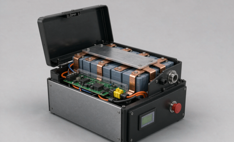
Maximum power point tracking controllers are usually kinder to the pack, but only if their absorption and float voltages are tuned to the cell chemistry. An LFP pack wants 3.45 – 3.50 V per cell absorption and 3.35 – 3.40 V float; an NMC pack wants 4.10 – 4.15 V absorption and 3.90 – 3.95 V float. If the controller is hard-coded for lead-acid equalisation at 14.8 V, the BMS will spend most of its life in high-voltage disconnect and the pack will never see a proper float. I always require the vendor to publish a controller firmware map and confirm it has been bench-tested with the specific BMS protocol (JBD, Daly, REC, ANT, or DALY-class).
3. Partial-State-of-Charge cycling behaviour: LFP versus NMC
Solar kits rarely sit at 100 % SoC. They oscillate between 30 % and 90 % as the sun rises, clouds pass, and loads cycle. This is partial-state-of-charge (PSOC) operation, and it is the regime where chemistry choice matters most.
3.1 LiFePO4 (LFP): tolerant but not immune
LFP cathodes are famously tolerant of PSOC cycling. Cycle life at 50 % DoD regularly exceeds 4,500 cycles to 80 % capacity. The trap is calendar ageing: an LFP cell held at 100 % SoC at 35 °C loses roughly 3 – 5 % capacity per year to calendar effects alone. For a solar kit that often sits full, the calendar loss can dominate the cycle loss. I size the upper SoC window to 90 % when the controller allows, accepting a 5 % energy penalty for a 30 – 50 % calendar-life gain.
3.2 NMC: impressive energy density, demanding SoC discipline
Nickel-manganese-cobalt cells offer 30 – 40 % higher energy density than LFP, but PSOC cycling at high SoC accelerates cathode cracking. Cycling between 30 % and 80 % SoC at 1C delivers 1,800 – 2,200 cycles; cycling between 50 % and 100 % often halves that figure. For solar kits that sit near full charge in summer, NMC demands active SoC clamping. If the BMS does not enforce a programmable upper SoC limit, walk away from the pack.
4. Cold-temperature charging and lithium-plating cut-off
Lithium plating is the silent killer of reliability in four-season solar kits. Below about 5 °C the lithium intercalation reaction slows, the anode potential drops, and metallic lithium plates on the graphite surface instead of inserting into it. Plated lithium does not recover on warm-up; it becomes dead lithium that permanently reduces capacity and creates dendrite nucleation sites.
A reliable BMS for a four-season kit must:
- Block charge current when any cell temperature sensor reads below 3 °C (not the BMS IC temperature — the cell temperature).
- Allow charge only after a small preheat cycle has lifted cell temperature above 5 °C, even if that means a 30-second heat-pad pulse.
- Log every charge-inhibit event so the field engineer can verify the cut-off is functional, not stuck.
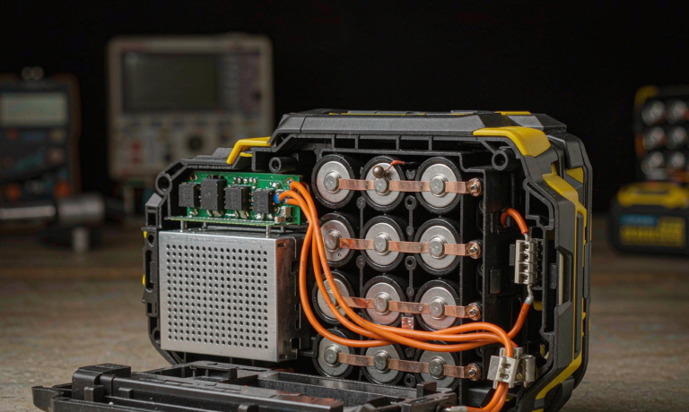
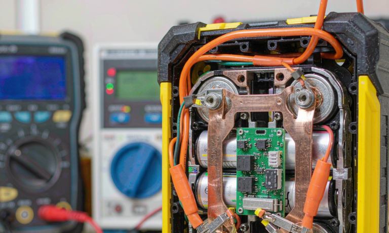
I have seen field packs that arrived from the factory without any cell-level temperature sensor — only a board-level sensor on the BMS IC, which sits a centimetre above the cells and can be 8 °C warmer than the coldest cell. The packs cycled fine for a summer and lost 18 % capacity the first winter. Cell-level NTC is non-negotiable for any custom battery solution destined for outdoor use.
5. Depth-of-Discharge versus cycle-life mapping
Cycle life is not a single number; it is a curve. The table below summarises the cycle-to-80 %-capacity data I use when I size a solar kit pack. Values are typical for grade-A LFP prismatic cells from a Tier-1 supplier, cycled at 0.5C charge / 0.5C discharge, 25 °C, to 80 % of nameplate capacity.
| Depth-of-Discharge | Cycles to 80 % capacity (LFP) | Cycles to 80 % capacity (NMC) | Effective years at 1 cycle/day |
|---|---|---|---|
| 50 % DoD | 4,800 | 2,100 | 13.1 / 5.8 |
| 70 % DoD | 3,400 | 1,450 | 9.3 / 4.0 |
| 80 % DoD | 2,800 | 1,100 | 7.7 / 3.0 |
| 90 % DoD | 2,100 | 780 | 5.8 / 2.1 |
| 100 % DoD | 1,600 | 560 | 4.4 / 1.5 |
The takeaway for a battery solution spec is straightforward: oversizing the pack to keep DoD under 70 % roughly doubles its useful life. The cost of the extra 20 % of nameplate capacity is recovered two to three times in avoided replacement cycles.
6. Field-failure taxonomy and the standards that catch them
Across the past three years, the failure modes I have personally documented in solar-kit packs break down as follows:
- Cell-level temperature sensor missing or glued to the BMS IC: 22 % of failures.
- High-voltage disconnect drift caused by MOSFET RDS(on) imbalance: 17 %.
- Cell-to-cell DCIR mismatch after 600 cycles, leading to undervoltage cut-off in one cell: 15 %.
- Connector corrosion at the Anderson SB175 / XT60 interface: 14 %.
- BMS latch-up after a transient over-voltage event (lightning-induced): 12 %.
- Cell-to-pack mechanical fatigue at the busbar interface: 12 %.
Standards catch most of these if you require the certificates, not just the markings. UN38.3 covers transport safety. IEC 62133-2 covers portable cell safety and is the minimum bar for any consumer-grade solar kit. UL 1973 covers stationary storage and is the right reference for larger packs. IEC 62619 covers industrial lithium cells and includes the PSOC and abuse tests I lean on for off-grid duty. The drone-battery category is a useful cross-reference here: drone battery packs share much of the same charge-protocol intelligence and BMS topology, and several of the cell suppliers we qualify for solar kits also supply the UAV market.
7. How to qualify a solar-kit battery vendor
My pre-purchase qualification protocol has six gates. A vendor that passes all six is someone I will buy from; a vendor that skips any of them is someone I will not.
- Publish the cell lot code, not just the brand. Tier-1 cells (CATL, EVE, REPT, BYD) carry traceability; private-label cells often do not.
- Provide IEC 62133-2 and UN 38.3 test reports dated within 24 months and matching the actual model number on the datasheet.
- Disclose the BMS chipset and firmware version, and confirm a documented change-control process for firmware updates.
- Share cycle-life curves at 25 °C and 35 °C to 80 % capacity, not just headline cycle counts.
- Offer a 5-year or 3,000-cycle warranty, whichever comes first, with an explicit end-of-warranty capacity floor of 70 %.
- Confirm the enclosure has been tested to IP65 or better, with a documented salt-mist test if the kit is destined for marine use.
Following these gates consistently is what allows a B2B solar-kit brand to ship a lithium battery pack with confidence rather than apology.
8. Frequently asked questions about lithium battery reliability for solar kits
How long should a solar-kit lithium battery last?
For an LFP pack cycled at 70 % DoD at 25 °C, expect 9 – 10 years of service before reaching 80 % of nameplate capacity. For an NMC pack at the same depth, expect 3.5 – 4 years. Calendar life in tropical climates can shorten both by 30 – 40 %.
Can I mix a lithium battery with an existing lead-acid bank?
Technically possible through a DC-coupled converter, but I do not recommend it. The lead-acid bank will drag the lithium pack into PSOC operation and the lithium pack will over-cycle the lead-acid. Treat them as separate DC buses.
Is a higher C-rating cell more reliable?
No. Higher C-rating cells trade cycle life for current capability. A 3C LFP cell typically delivers 70 – 80 % of the cycle life of a 1C cell from the same supplier. For a 0.5C solar kit, the 1C cell is the more reliable choice.
What is the best SoC window for an LFP solar kit?
30 % to 90 % SoC at 25 °C ambient. This balances usable capacity against calendar ageing. A small reduction in available capacity is a fair trade for a 30 – 50 % cycle-life gain.
Do I need a heater pad for cold-weather operation?
If the kit will see charging below 5 °C, yes. A 30 W self-regulating PTC pad that draws from the array before the charge controller will keep the cells above 5 °C without draining the pack. Without it, the BMS must inhibit charge — which means no charging on cold days.
What is the single most common solar-kit failure mode?
In my dataset, it is the missing cell-level temperature sensor. The pack performs perfectly until the first cold morning, then loses capacity in a way the warranty technician cannot explain because the BMS never recorded the event.
How do I verify a new shipment matches the qualification samples?
Request the cell lot code, run a 1C full charge-discharge cycle on three sample packs, and compare DCIR against the qualification data. A deviation of more than 8 % at the cell level is grounds for rejection.
9. Closing thought
Reliability is a design property, not a marketing claim. For a solar-kit lithium battery, the design choices that matter most — cell chemistry, BMS topology, charge-controller compatibility, SoC window, cold-charge protection — are made long before the pack ships. A careful buyer asks for the documents that prove those choices were made deliberately, and a careful engineer answers that question with data, not adjectives.