Lithium Battery Pack Busbar Design and Current Density Limits
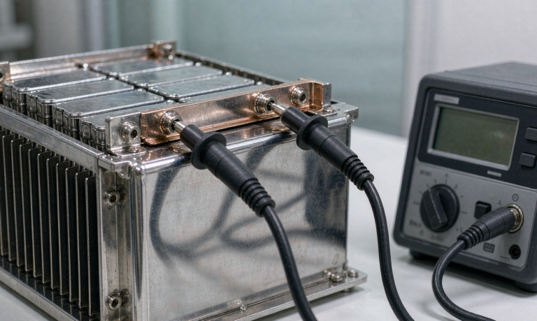
When a customer asks me to push more current through a lithium battery pack, the cells are rarely the bottleneck. In my fifteen years designing packs at Horizon Power, the component that quietly decides whether a 100 A or 200 A rating is realistic is the busbar. A busbar is the solid metal strip that links cells or modules together, and its cross-section, material, and connection method set a hard ceiling on current density. Get it wrong and you get hot spots, voltage sag, and in the worst case a thermal event that no amount of cell-level protection can fix.
In this guide I will walk through how we size busbars for lithium battery packs, the current density limits we use in production, and the safety margins that keep a pack within UN38.3 and IEC 62133 expectations.
Why Busbar Design Defines Pack Current Capability
A lithium battery pack is only as strong as its weakest series link. The busbar carries the full pack current between parallel groups, so every amp that leaves the pack also crosses every busbar joint. Unlike a wire, a busbar is a fixed geometry: its resistance is set the moment you choose the material, thickness, and width. We model it early in the mechanical layout because changing it later means re-tooling the cell holder and the laser-welding fixture.
The first number I look at is not capacity but continuous current divided by busbar cross-section. That ratio, current density, tells me whether the strip will stay cool or slowly cook the pack. A drone battery that draws 60 A peak through a 2 mm thick, 10 mm wide nickel strip is already running near the edge, which is why high-rate packs move to copper or nickel-plated copper busbars.
Current Density Limits for Lithium Battery Busbars
For nickel-plated steel busbars, which are common in cylindrical cell holders, we hold continuous current density to about 4 A per square millimeter and peak, sixty second, to about 8 A per square millimeter. Pure nickel is better at roughly 6 A per square millimeter continuous. Copper busbars, with conductivity near 58 megasiemens per meter, comfortably carry 8 to 10 A per square millimeter continuous and 15 to 20 A per square millimeter for short pulses. Aluminum sits between, around 5 to 6 A per square millimeter continuous, but it needs careful surface treatment to stop oxidation at the joint.
These are not arbitrary numbers. They come from balancing temperature rise against the pack enclosure’s ability to shed heat. Inside a sealed case with still air, a strip running at 10 A per square millimeter in copper still climbs several degrees per minute, so we derate for duty cycle. A custom battery solution that runs a thirty percent duty cycle can use a higher density than one running flat out for an hour.
Material Choices: Copper, Aluminum, and Nickel-Plated Steel
Copper is the default for high-current lithium battery packs. It is expensive and heavy, but its low resistance means thin bars can carry serious current. We use tin or nickel plating on copper to stop verdigris and to make ultrasonic or laser welding consistent.
Nickel-plated steel is the workhorse of consumer 18650 and 21700 packs because spot welding nickel to the cell cap is fast and reliable. The trade-off is higher resistance, so you need more cross-section for the same current. Aluminum is lighter and cheaper than copper but demands ferrite or laser cleaning at the joint; a dirty aluminum interface can double contact resistance overnight.
For an LFP battery used in stationary storage, weight matters less than cost, so we often choose thick tinned copper. For a NCM battery in a mobile device where every gram counts, aluminum busbars with plated joints earn their place.
Cross-Section Sizing and the 4 A per Square Millimeter Rule
The quick field rule I teach new engineers is 4 A per square millimeter of busbar cross-section for nickel-based strip under continuous load. A 2 mm by 10 mm strip gives 20 square millimeters, so it is good for about 80 A continuous. If the application is a 12v lithium battery in a trolling motor pulling 50 A, that strip has comfortable margin. If it is a 120 A power pack, we double the section or switch to copper.
Sizing is not just area. Width spreads heat better than thickness because more surface faces the air. We prefer wide, thin bars over narrow, thick ones when space allows. The section must also survive the weld: a 0.2 mm foil welds cleanly, while a 3 mm bar needs a pre-weld and a penetration check.
Connection Methods: Welding, Bolting, and Busbar Rivets
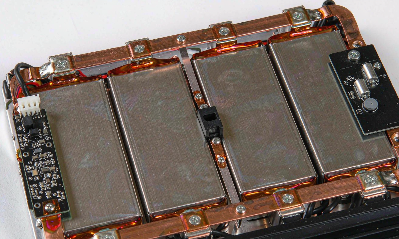
How the busbar meets the cell decides whether your calculated resistance is real. Laser welding gives the lowest, most repeatable resistance on prismatic terminals and is our choice for automotive-grade lithium ion battery modules. Ultrasonic welding suits foil-to-busbar tabs and leaves no heat-affected zone in the cell. Resistance spot welding is cheap for nickel strip on cylindrical cans but drifts with electrode wear, so we audit weld strength weekly.
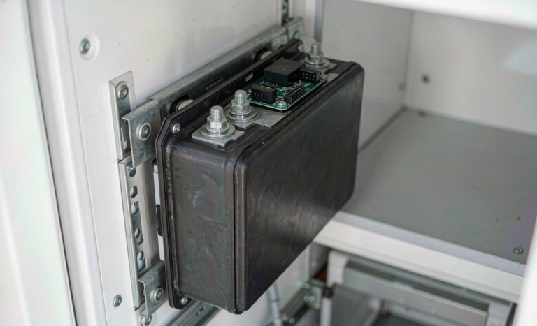
Bolted joints are serviceable and let you open the pack, but every bolt is a resistance point. We specify spring washers and a torque window, then verify with a milliohm test. Busbar rivets are a middle path for modular packs that must be field-repairable without special welders.
Busbar Layout: Series, Parallel, and Hybrid Topologies
The geometry of the busbar matters as much as its material. In a series layout the same current runs through every link, so each busbar must carry the full pack current and the section is uniform. In a parallel group the current splits, so the busbar that collects the group current is the thick one while the intra-group links carry only a share. I have seen packs where the parallel busbar was sized for the cell current and then used as the series link by mistake, overheating on the first full discharge.
Hybrid topologies, common in a high-voltage lithium ion battery module, use wide copper bars to gather many parallel strings and thin nickel links between series groups. The rule is simple: draw the current path, find the highest current any one bar carries, and size that bar first. We color-code the current path in the CAD model so a reviewer can see the peak at a glance before the first prototype is cut.
Thermal Rise, Voltage Drop, and Safety Margins
Two numbers close the loop. First, voltage drop: I equals V over R, and a busbar at 1 milliohm dropping 0.1 V at 100 A is wasting 10 W as heat. Second, temperature rise: we simulate the strip in still air and derate until the steady-state surface stays below 60 degrees Celsius inside the case. That 60 degree figure protects the cell seals and the surrounding polymer parts.
We also watch the joint, not just the bar. A perfect copper bar with a poor weld can carry half its rated current before the joint glows. Our production test is a four-wire milliohm measurement across every series busbar after welding; any joint above the design limit is cut and reworked. This step is cheap insurance against field failures that no battery management system can see until it is too late.
Safety margins are where experience shows. We never run a busbar at its calculated limit. A thirty percent margin on current density covers plating variation, dust on contacts, and the day the cooling fan fails. This discipline is what lets a pack pass IEC 62619 and UL 1973 abuse tests without the busbar becoming the failure point.
Frequently Asked Questions
What current density is safe for a lithium battery busbar?
For nickel-plated steel we hold about 4 A per square millimeter continuous and 8 A per square millimeter peak. Copper busbars are safe near 8 to 10 A per square millimeter continuous. Always derate for duty cycle and enclosure heat.
How do I size a busbar for a 100 A lithium battery pack?
Plan for at least 25 square millimeters of cross-section in copper, or about 50 square millimeters in nickel strip, then verify with a temperature-rise test in the real enclosure. The 4 A per square millimeter rule gives a 120 A rating on a 30 square millimeter nickel bar, leaving margin.
Is copper or aluminum better for battery busbars?
Copper carries more current per gram and per millimeter, welds cleanly, and resists corrosion with plating. Aluminum is lighter and cheaper but needs surface preparation at joints. Choose copper for high-rate packs and aluminum when weight and cost dominate.
Can busbar current limits affect UN38.3 or IEC 62133 compliance?
Yes. A busbar that overheats or develops a high-resistance joint can trigger the thermal and short-circuit tests in UN38.3 and the safety requirements in IEC 62133. Proper sizing and welding are part of passing those standards.
How does busbar resistance impact pack runtime?
Every milliohm in the busbar wastes energy as heat instead of reaching the load. A pack with 2 milliohm of busbar loss at 100 A sheds 20 W, which shortens runtime and heats the case. Lower-resistance copper busbars recover that capacity.
Further Reading
References