Semi-Solid State Battery Dry Electrode Processing
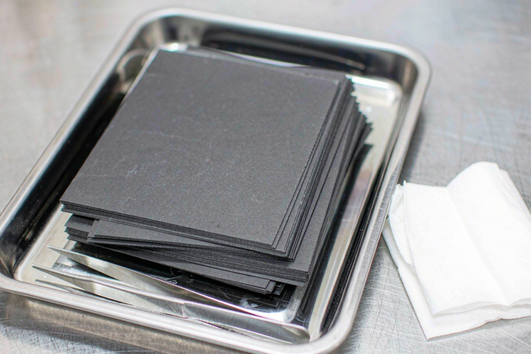
Every solvent we remove from a factory is a problem we no longer have to solve. That is the honest argument for dry electrode processing, and on semi-solid state battery programs it gets stronger rather than weaker. In a conventional lithium battery the solvent is a processing aid that leaves. In a semi-solid state battery the gel electrolyte stays against every square millimeter of electrode surface for the life of the product, so anything the electrode carries into that interface travels with it. This guide covers the dry route as I have qualified it on our own pilot line: fibrillation, blending, roll lamination, thick-film densification, and the release gates for a semi-solid build.
Why Solvent-Free Electrodes Matter More in a Semi-Solid Cell
A wet-coated electrode that comes off a well-run oven still carries 200 to 600 ppm of residual NMP by headspace GC. In a liquid-electrolyte cell that residue dissolves into a large electrolyte volume and is consumed during SEI formation. A semi-solid state battery has no such reservoir. The liquid phase in a gel system is typically 10 to 20 weight percent, and it is held in a polymer network that slows diffusion by one to two orders of magnitude relative to a free liquid. Residual solvent does not dilute; it concentrates where it was left.
The second reason is binder migration, which surprises teams moving from wet to dry. When a PVDF-based slurry dries, the binder travels with the solvent front toward the free surface and leaves a binder-rich skin, which is a diffusion barrier for gel precursor. We have measured 30 to 60 percent interfacial impedance differences between the separator side and the collector side of the same wet electrode from this effect alone. A dry blend has no liquid phase to carry the binder anywhere. For a semi-solid state battery, where gel ingress is the rate-limiting step in assembly, that is worth more than the energy savings everyone talks about.
PTFE Fibrillation: The Binder Mechanism That Replaces Casting
Dry processing works because PTFE is not a binder in the wet sense. Under shear at 40 to 80 degrees Celsius, PTFE particles draw into fibrils 10 to 100 nanometers in diameter, and those fibrils form a web that mechanically locks active material and conductive carbon together. Loading is 1.0 to 2.5 weight percent against 2 to 4 percent for PVDF in a wet formulation, which gives back that much active material.
Getting the shear window right
The window is narrower than most process sheets admit. Too little shear and the fibrils never form, so the film crumbles at the first nip; too much and they over-draw and shorten, and the film turns brittle. We qualify each PTFE lot with a mixing ladder from 4 to 20 minutes at fixed tip speed, measuring film tensile strength and elongation. The usable plateau is usually 8 to 14 minutes, and it moves with lot and powder moisture.
Where PTFE is the wrong answer
PTFE is electrochemically reduced at low anode potentials, so the classic dry route is a cathode process. On the anode side we have had better results with aqueous-processable systems or alternative dry binders, and we accept the extra handling. There is also a gel compatibility test: soak a free-standing film in gel precursor for 72 hours at 45 degrees Celsius and measure swell and adhesion retention. Our limit is under 5 percent swell and over 80 percent retention. A binder that swells in the gel plasticizer will close the very pores the electrolyte needs to enter.
Dry Mixing and Powder Blending Before the Rolls
Order of addition decides whether the roll press has a chance. We disperse active material with conductive carbon first at high shear, then add PTFE last and fibrillate at controlled energy. Adding PTFE early means the step that should deagglomerate carbon instead destroys the fibril network.
Moisture matters more than people expect. Cathode powders carry surface lithium hydroxide and lithium carbonate, both hygroscopic. We condition powders at 60 to 80 degrees Celsius and blend below 1 percent relative humidity, checking by Karl Fischer with 130 to 180 degrees Celsius oven extraction. A blend that picks up 900 ppm of water going into the rolls shows up later as formation gas, and a gel cell has little liquid volume to absorb it.
Segregation and combustible dust
Dry blends segregate: vibration during transfer moves fine carbon away from coarse active particles, so conductive paths vary across the web. We sample top, middle and bottom of every tote and check by loss-on-ignition and four-point resistivity. A cathode and carbon blend is also a combustible dust. NFPA 652 requires a dust hazard analysis, bonding and grounding are verified, and we treat the mixing and feeding area as a classified location. This is where the dry route trades a solvent problem for a dust problem, and the trade has to be managed explicitly.
Roll Pressing and Hot Lamination
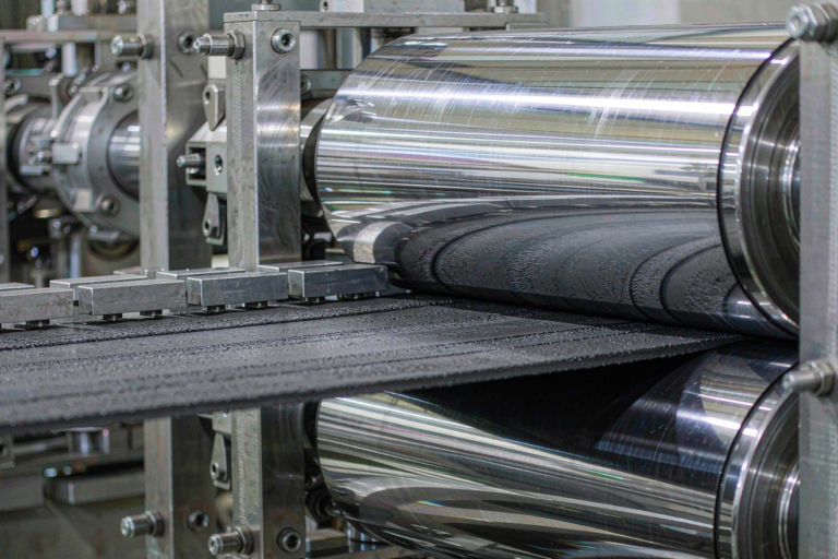
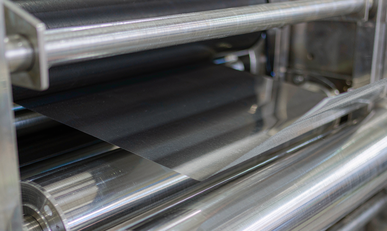
The powder becomes a film in the first nip at a wide gap, then the gap closes 10 to 20 percent per pass across three to five nips. Roll temperature runs 80 to 140 degrees Celsius for PTFE-bound cathodes. For lamination we use carbon-primed aluminum foil with a 0.5 to 1.5 micron conductive primer, a lamination nip at 100 to 160 degrees Celsius, and line loads of 300 to 800 newtons per millimeter. Line speed on a dry line is 15 to 40 meters per minute against 40 to 80 for modern wet coating, and that speed gap is the honest cost of the route today.
Adhesion is the hard gate
The primer is not optional. Dry films on bare foil give 5 to 12 newtons per meter in a 180 degree peel; the same film on primed foil gives 18 to 30. Our release limit is 15 newtons per meter minimum, measured as-laminated and after electrolyte soak, because a film that holds in air can let go once the gel plasticizer gets between it and the foil.
Failure modes we see most
Over-rolling produces an orange-peel surface and a closed pore structure the gel cannot enter. Edge cracking comes from roll deflection and is usually a crown or gap-levelling problem rather than a formulation one. White specks are unfibrillated PTFE, almost always a mixing energy shortfall rather than a dispersion problem. Springback of 2 to 6 percent measured 24 hours after calendering is normal and belongs in the thickness target, not discovered at stack height.
Thick Electrodes and Ionic Transport
This is where the dry route earns its keep. On our wet line we cap single-sided dry thickness near 140 to 160 microns before calendering, since going thicker risks solvent entrapment and cracking. Dry films reach 200 to 350 microns without a drying step, taking areal capacity from 3 to 4 milliamp hours per square centimeter up to 4.5 to 6.5. Fewer layers for the same capacity means less foil, less separator and fewer welds, and fewer gel-filled interfaces, where most interfacial impedance lives.
Tortuosity is the bill
Thickness is free only up to the point where ionic transport pays for it. At 35 percent porosity a 300 micron cathode losing 8 to 12 percent of capacity at 2C against a thin electrode is normal, and the fix is not more pressure. Options that have worked include pore formers driven off after lamination, laser-ablated channels 30 to 60 microns wide on a 200 to 500 micron pitch, and two-layer structures with coarse particles near the collector and fine particles near the separator. Each costs energy density or capex, so the decision is per application.
Impregnation time scales badly
Capillary fill time scales roughly with the square of thickness, so doubling thickness quadruples the dwell needed for gel precursor to reach the collector. We run vacuum impregnation at 45 to 60 degrees Celsius and verify by weight uptake plus electrochemical impedance spectroscopy at 12, 24 and 48 hours. If the Nyquist plot is still moving between 24 and 48 hours, the electrode is not impregnated, and no formation tuning will fix it.
Defects, Metrology, and Release Gates on a Dry Line
Inline metrology on a dry line is less forgiving: there is no coating die to trim and no oven to hide variation. We run beta transmission for areal weight at plus or minus 1.5 percent of target, laser caliper for thickness at plus or minus 2 percent, and infrared on every roll face because roll temperature drift shows up as adhesion drift about twenty meters downstream.
The gate set we actually use
- Areal weight within plus or minus 1.5 percent, checked at start, mid and end of every master roll
- Thickness within plus or minus 2 percent after 24 hour springback, not at the nip
- Peel adhesion at least 15 newtons per meter, as-laminated and after 72 hour gel soak at 45 degrees Celsius
- Four-point resistivity distribution, with the tail reported rather than the mean
- Karl Fischer water under 200 ppm on the finished film
- Mandrel bend at one millimeter with no cracking, every lot
Cell-level proof comes after the film gates. For dry cathodes with a gel electrolyte we expect 1.5 to 3 milliliters of formation gas against 2 to 5 for a wet reference and at least 80 percent retention after 500 cycles at 1C. Every qualification ends with a cross-section, because looking is the only way to know whether gel reached the collector.
None of the usual standards care how you made the electrode. UN 38.3 covers transport, IEC 62619 industrial cells, IEC 62133-2 portable, UL 1973 stationary and UL 9540A propagation. They prove the product passed, not that the process is controlled, and on a dry line the process is where the risk moved. Any change to PTFE lot, mixer energy, roll temperature or primer supplier triggers the full gate set again.
Frequently Asked Questions
Can a dry electrode match the energy density of a wet-coated one?
Yes, and often beat it by 3 to 6 percent. You save 1 to 2 percent binder loading, you avoid the binder-rich skin that blocks gel ingress, and you can run thicker coatings with fewer collector and separator layers. The gains disappear if you over-calender to chase density, because closing porosity hurts a semi-solid state battery more than it helps.
Does dry electrode processing work for the anode side too?
Not with PTFE, which is reduced at low anode potentials, so the classic dry route is a cathode process. For graphite or silicon-blend anodes we use aqueous-processable binder systems or alternative dry binders, and we accept the extra handling. The impregnation and adhesion gates are the same on both sides.
How much energy does removing the coating oven actually save?
Coating and drying is the largest single energy consumer in an electrode plant, and the NMP recovery train adds both energy and capital. On our own accounting, eliminating both cut electrode-area energy by roughly 30 to 40 percent. The saving is partly offset by higher roll press power and a dry room that still has to be dry.
Is a dry electrode line cheaper to build?
Less than the headlines suggest. You delete the oven, the solvent recovery train and a large share of dry room volume. You add a multi-nip roll press train with tight temperature control and powder handling built to combustible dust rules. Payback depends more on energy prices and NMP recovery cost than on the press itself.
Does a dry electrode still need a dry room?
Yes, just a smaller one. You no longer need a long drying oven inside the controlled space, but blending, lamination and stacking still run at low dew point because cathode powders are hygroscopic and the gel precursor is moisture sensitive. Most of the saving is in dry room volume and air handling load.
How do you prove the gel electrolyte has fully impregnated a thick dry electrode?
Three ways together: weight uptake against calculated pore volume, electrochemical impedance spectroscopy at 12, 24 and 48 hours to confirm the spectrum has stopped moving, and a cross-section to confirm gel reached the current collector. Any one alone will let a bad build through.
Further Reading
References