
Battery Solution Integration for Robotics
I have lost count of how many robotics programs I have joined at the point where the cells were already chosen, the capacity was already approved, and the schedule was already late. The pack worked on the bench. It failed in the robot. In almost every one of those projects the root cause was not chemistry and not capacity — it was integration. A robotics battery solution is not a box of cells you drop into a chassis; it is a mechanical joint, a high-current electrical node, a communication peer, and a serviceable field-replaceable unit, all at once. Get any one of those four wrong and you will chase intermittent faults for months.
I am Karl Huang, a senior lithium battery engineer. Most of my working life has been spent on the unglamorous side of pack design: torque values, contact resistance, connector derating, CAN handshakes, and the commissioning paperwork that proves a fleet is safe to run unattended. This article is the integration playbook I hand to robotics customers before we cut the first bracket. Here I assume the cells are adequate and ask a narrower question: what does it take to make the pack and the robot behave as one machine?
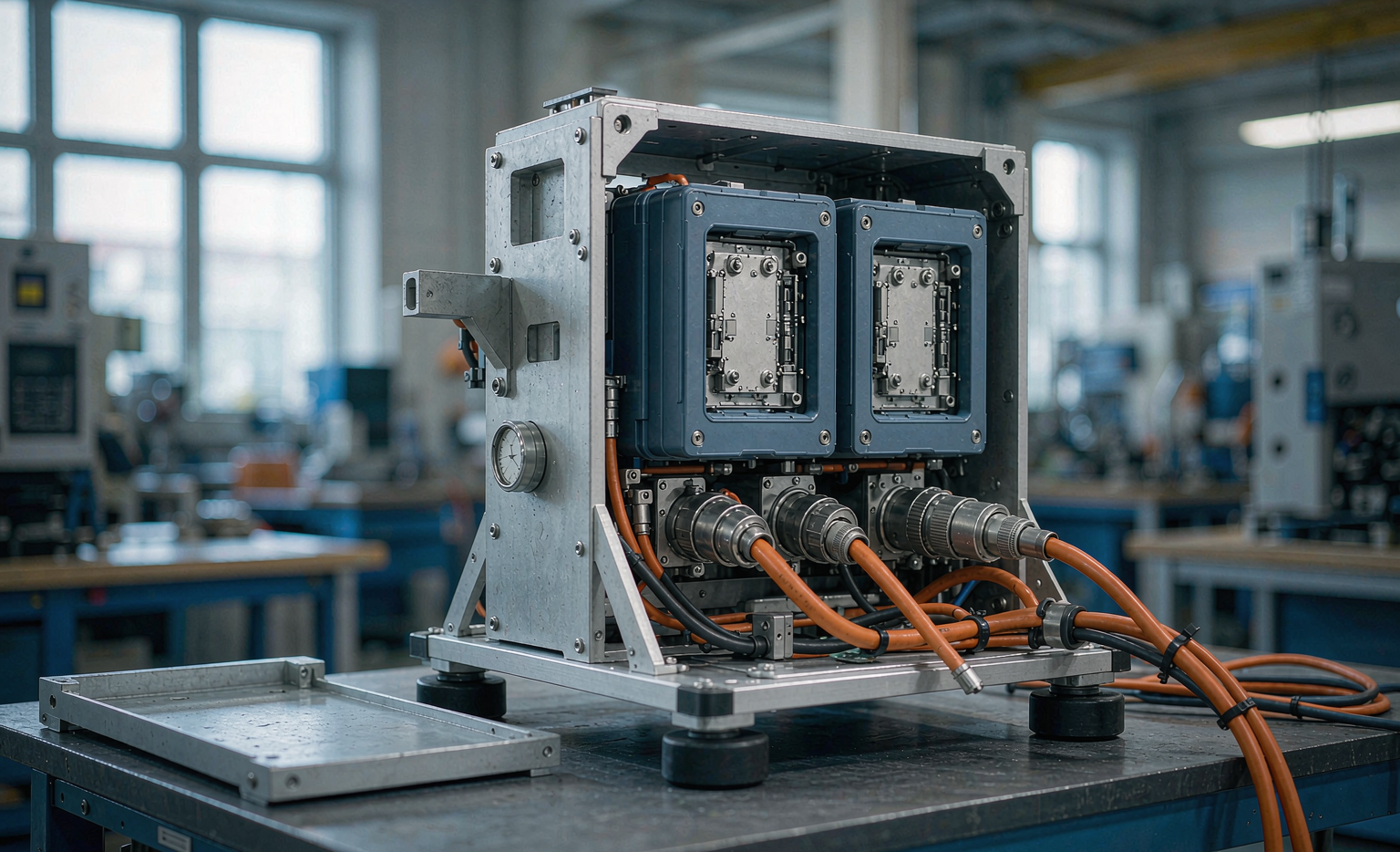
My framing rule is simple. Integration is finished when three interfaces are frozen and documented: the mechanical interface (how load moves between pack and chassis), the power interface (how current and fault energy move), and the data interface (how state of charge, limits, and faults move). A robotics battery solution that has all three frozen can be manufactured, serviced, and fleet-managed. One that has only capacity and voltage frozen will be redesigned at least twice.
Integration Starts With the Duty Cycle, Not the Enclosure
Before any bracket is drawn I ask for a logged duty cycle, not a specification sheet. For autonomous mobile robots (AMRs) and AGVs the numbers that drive integration are rarely the ones in the requirements document. What I need is the continuous traction current during loaded travel, the peak current during acceleration and lift events, the dwell time at each charging opportunity, and the ambient temperature at floor level near the drive motors.
A typical warehouse AMR I worked on last year showed 18 A continuous at 48 V during loaded transit, 95 A peaks lasting 1.2 s at each acceleration, and 340 acceleration events per hour. The customer had specified a 60 A continuous pack because that is what the motor controller nameplate said. The real integration constraint was not the 60 A rating — it was 340 thermal pulses per hour through the connector and busbar joints. That is a fatigue and contact-resistance problem, and it changes connector selection, not cell selection.
Two numbers I hold customers to. Size continuous current capability at 1.25× the logged 95th-percentile current, not the nameplate. And count every pulse above 2 C as a thermal event, because contact resistance growth at a working joint scales with I²t. A well-specified lithium battery for robotics is defined by its pulse census as much as by its watt-hours.
Mechanical Integration: Cradles, Preload, and Vibration Reality
Robots vibrate differently from vehicles. The excitation is not road-random; it is dominated by narrow-band content from drive wheels, castor flutter, and floor joints, typically 8–120 Hz, with sharp shocks when a wheel crosses a dock plate. I have measured 6 g half-sine shocks of roughly 11 ms duration in an ordinary distribution centre.
My mechanical rules for a robotics battery solution:
- Constrain the pack in six degrees of freedom, but load it in one. A cradle with a machined pocket that takes lateral and longitudinal load in shear, plus a top clamp that provides vertical preload, is far more robust than four bolts through a flange trying to do everything.
- Preload the module stack, do not just retain it. For prismatic and pouch formats I target a stack pressure in the range specified by the cell supplier — commonly 0.1–0.4 MPa for pouch designs — and I verify it with a load cell shim on the first article, not with a torque wrench alone.
- Isolate, but do not float. Elastomeric pads between cradle and chassis with a natural frequency below 25 Hz cut high-frequency energy into the cells. Fully floating mounts let the pack swing and pull on the power harness, which is how I have seen connector housings crack.
- Design the removal path first. If a technician cannot swap the pack in under two minutes with one hand on a torch, the fleet will run degraded packs because nobody wants to do the job.
Vibration qualification is where mechanical integration gets proven. I run modules through the sine and random profiles of UN38.3 Test T.3 as a baseline, then add a durability profile derived from the measured floor spectrum, typically 25 hours per axis. The acceptance criteria I use are no measurable change in insulation resistance (≥1 MΩ at 500 VDC), no more than 10 % growth in joint contact resistance, and no change in cell open-circuit voltage spread beyond measurement noise.
Electrical Integration: Connectors, Inrush, and the Fault Path
The power interface is where most field failures are born. Three issues appear again and again.
Connector derating is not optional. A connector rated 120 A on a datasheet is rated at 20 °C ambient in free air with a specified conductor size. Inside a robot at 45 °C, in a bundle, with a shorter cable than the test setup, the honest working figure is often 60–70 % of nameplate. I specify the connector against measured temperature rise: mating interface must stay below 65 °C at worst-case continuous current in the real installation, measured with a thermocouple on the contact barrel, not the housing.
Inrush must be managed by design. Robot controllers have large DC-link capacitance. Closing a contactor into an uncharged link can produce hundreds of amps for a few milliseconds, which welds contacts over time and trips overcurrent protection intermittently. Every robotics pack I ship now includes a pre-charge path — a resistor and auxiliary contactor sequenced by the BMS — sized so the link reaches 95 % of pack voltage before the main contactor closes. I verify closure sequencing on an oscilloscope during commissioning and record the trace in the design file.
The fault path must be independent of firmware. Software protection is necessary but never sufficient. My layered scheme is: cell-level and pack-level fuse coordination as the last resort, an independent hardware overvoltage and overtemperature comparator that can open the contactor without the microcontroller agreeing, and firmware limits as the first line. I prove independence by injection testing — deliberately holding the MCU in reset and confirming the hardware layer still opens the contactor within its specified time.
In a robot the chassis is usually the EMC reference: bond the pack enclosure to chassis with a defined low-impedance strap, keep the DC negative isolated from chassis, and verify isolation monitoring from the robot side. Mixing a floating enclosure with a chassis-referenced negative produces sensor-bus noise that gets blamed on the LiDAR for six weeks.
Data Integration: The BMS-to-Controller Handshake
A robotics battery is a peer on the machine’s control network, and the quality of that conversation determines whether the fleet manager can plan work. I insist on four things in the data interface specification.
- Declared limits, not just measurements. The BMS must publish instantaneous charge and discharge current limits, refreshed at 10 Hz or faster, and the robot controller must obey them. Publishing state of charge alone pushes the thermal decision onto a controller that has no cell temperature data.
- A heartbeat with defined failure behaviour. If the BMS message stops, the controller must ramp to a safe stop rather than continuing on the last value. I specify a 200 ms timeout for limit messages in most designs.
- State of health that means something operationally. Reporting capacity fade percentage is fine for reports, but the fleet needs predicted remaining runtime under the current load. That calculation belongs in the pack, where the cell model lives.
- A stable, versioned protocol. Every signal gets an ID, a scale, a unit, and a version number in a document under change control. Undocumented CAN changes between prototype and production are the single most common cause of late integration failures I see.
For AMR fleets I also expose a small diagnostic log — peak currents, temperature excursions, count of protection events — retrievable over the same bus. When a robot starts underperforming, that log answers in ten minutes what would otherwise take a week of arguing between the battery supplier and the robot builder. Building this into a custom battery solution costs almost nothing at design time and saves enormous field cost.
Charging Integration: Docks, Opportunity Charging, and Fleet Math
Robotics fleets rarely charge the way the pack was characterised. Opportunity charging — frequent short top-ups at a dock between tasks — is now the norm, and it changes the integration requirements in three ways.
First, contact-based docking means high current through a blade or sliding contact with imperfect alignment. I specify the dock interface to tolerate misalignment within a contact resistance budget, and require the BMS to ramp current only after stable contact is confirmed electrically — not after the navigation stack believes it has docked.
Second, low-temperature charge acceptance becomes a scheduling constraint. A pack returning from a chilled area at 4 °C cannot accept full charge current without lithium plating risk. My integration deliverable is a charge-acceptance table by temperature that the fleet manager can consume, so the scheduler stops assigning a 12-minute top-up to a robot that physically needs 30 minutes at that temperature.
Third, partial-state-of-charge cycling dominates the ageing model. Continuous shallow cycling in the mid state-of-charge band is generally gentler on a lithium battery than deep cycles, which is good news, but it requires the state-of-charge estimator to be robust without regular full-charge recalibration. I schedule a deliberate full charge and rest at a defined interval — often weekly, per fleet — purely to re-anchor the estimator, and I write that requirement into the integration document rather than hoping it happens.
Compliance and Safety Integration
Robotics packs live under a stack of requirements that must be reconciled early, because each one constrains hardware.
- UN38.3 for transport is version-locked to a specific bill of materials. Changing a cell supplier, a connector, or the enclosure after testing can invalidate the report. I keep a table mapping each test report to the exact BOM revision.
- IEC 62619 is my working standard for industrial secondary lithium cells and batteries, covering thermal propagation and functional safety expectations. IEC 62133 remains relevant for portable applications and smaller service packs.
- ISO 3691-4 governs driverless industrial trucks and their systems; the safety-related control functions it demands determine whether the pack’s protection needs to be part of a rated safety function or merely a protective device.
- IEC 61000-series EMC testing must be done at machine level, not pack level. A pack that passes in a test fixture can still fail in the robot because the harness routing changed the coupling path.
- For airborne platforms in mixed robotics portfolios, the same discipline extends to a drone battery under FAA and EASA operational rules, where state-of-charge reporting accuracy directly limits mission planning margins.
Compliance is an integration input, not a downstream gate. Told in month one that a machine falls under ISO 3691-4, we design the protection architecture once; told in month eight, we redesign it.
Commissioning: What a Signed-Off Integration Looks Like
Integration is complete when I can hand over a package, not an opinion. My sign-off set for a robotics battery solution contains eight items:
- Measured contact resistance and temperature rise at every power joint, at worst-case continuous current in the installed configuration.
- Oscilloscope traces of pre-charge and main contactor sequencing at cold and hot extremes.
- Protection independence test log, including MCU-held-in-reset injection results.
- Insulation resistance and hipot results after the durability vibration profile, not before.
- The versioned communication matrix, with heartbeat timeout behaviour demonstrated on the actual robot.
- Charge-acceptance table by temperature, in the format the fleet scheduler consumes.
- Torque and joint specifications with first-article measured values, not target values.
- A change register that names which test reports are invalidated by which categories of change.
That package is what allows a fleet to scale from three robots to three hundred without relitigating the battery. It is also what lets us reuse the architecture across adjacent products. The same discipline that produces a good robotics pack transfers directly to a home energy storage system, where string architecture and protection independence matter just as much, and to emerging chemistries — I have run the same integration checklist on sodium-ion battery prototypes and on semi-solid state battery samples with almost no modification, because the interfaces are chemistry-agnostic even when the cells are not.
Frequently Asked Questions
How early should battery integration work start in a robotics program?
At concept, alongside the chassis layout. The pack envelope, removal path, harness routing, and dock interface all compete for the same space as drive motors and sensors. In my experience, teams that fix the pack envelope after the chassis is designed lose more schedule than teams that fix the cell choice late.
Can I reuse a standard pack instead of a custom battery solution?
Often yes, and I recommend it when the duty cycle fits. The decision hinges on the three interfaces. If a standard pack’s mechanical mounting, connector rating, and communication protocol all suit your machine, use it. If two of the three need adaptation, a custom battery solution is usually cheaper than a bracket-and-adapter stack that nobody documents.
What is the most common integration mistake you see?
Trusting connector and contactor nameplate ratings without measuring temperature rise in the real installation. It is a quiet failure mode: nothing breaks in validation, then contact resistance climbs over a year of thermal pulses and the fleet starts reporting random shutdowns under load.
How do I stop the BMS and robot controller from disagreeing about limits?
Make the pack the single authority on current limits and make the controller’s obedience an acceptance test, not an assumption. Then verify the heartbeat timeout behaviour by physically unplugging the bus during commissioning and confirming the robot ramps to a safe stop.
Does opportunity charging shorten pack life in robotics fleets?
Not inherently. Frequent shallow cycling in the mid state-of-charge band is generally kinder to a lithium battery than deep discharge cycling. The risks are charging cold without a temperature-based current limit, and state-of-charge estimator drift from the absence of full-charge recalibration. Both are solvable in the integration specification.
What documentation should I demand from a battery supplier?
Measured values rather than targets: joint resistances, temperature rises, contactor sequencing traces, protection injection logs, and the versioned communication matrix.
Closing Thoughts From the Workshop Floor
The best robotics battery programs I have worked on were not the ones with the most advanced cells. They were the ones where the mechanical engineer, the power electronics engineer, and the software lead signed the same three interface documents. Cells improve every year; interfaces are where projects are won or lost. Treat integration as an engineering deliverable with measured evidence behind it, and your fleet will run.





