
Battery Solution Performance for Equipment
When a procurement manager tells me they need a “high-performance battery,” I have learned to pause. Performance is not a single number. For equipment it is a triangle of energy, power, and lifetime, warped by the operating environment. Over the last decade as a senior lithium battery engineer at Horizon Power, I have specced custom battery solutions for everything from handheld test gear to 40-ton mining trucks. The gap between a cell’s datasheet and a battery solution that survives three winters on a job site is where real engineering lives. In this article I will walk through how we turn a vague “make it last longer and hit harder” request into a validated battery solution, and where most equipment programs quietly go wrong.
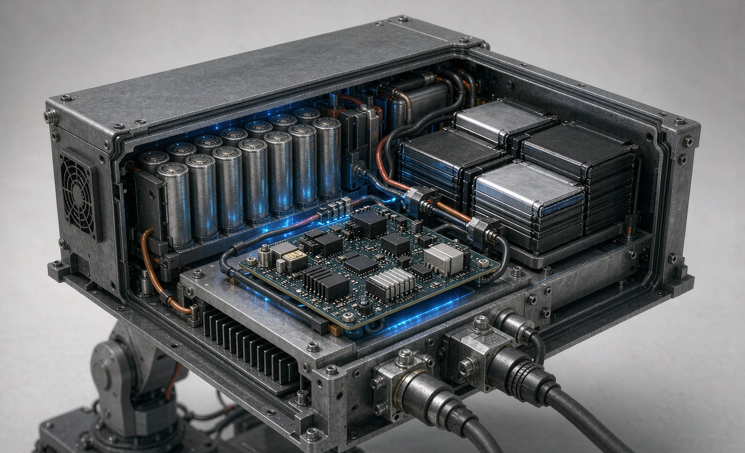
What “Performance” Actually Means for an Equipment Battery Solution
Performance for equipment is rarely about peak discharge alone. The duty cycle defines it. A robotic arm may need 1C continuous with 5C for 200 ms during a pick-and-place; a portable compressor needs 3C for 10 seconds every 40 seconds. If you size the battery solution for the average and forget the pulse, you get voltage sag, premature aging, or a tripped BMS. We model the actual load profile, not the nameplate. For a recent custom battery solution for a hydraulic power unit, the datasheet claimed 2 kW average; the real telemetry showed 6 kW peaks at a 1:9 duty ratio. That single measurement changed the cell selection from NMC to a high-rate LFP and reshaped the entire thermal path. Equipment is unforgiving precisely because its load is never the smooth curve the marketing slide implies.
Choosing the Lithium Battery Chemistry That Fits the Workload
The lithium battery at the heart of any equipment battery solution carries hard trade-offs, and the numbers matter more than brand:
- LFP (LiFePO4): 160-200 Wh/kg, 3,000-5,000 cycles, flat voltage, excellent thermal stability, 55-70% capacity at -20 C. Cell cost typically 90-120 USD/kWh. Best for cycle-life-critical and safety-critical equipment.
- NMC (NMC811): 220-280 Wh/kg, 1,000-2,000 cycles, higher energy density, 110-150 USD/kWh. Used where mass and volume are constrained.
- NCA: 250-300 Wh/kg, favored in aerospace and high-power tools where every gram is paid for.
- Semi-solid state: 300-360 Wh/kg emerging, with a higher thermal margin – a promising path for next-generation equipment battery solutions where both energy and safety budgets are tight.
We rarely pick on energy alone. For a drone battery pack the weight penalty of LFP is unacceptable, so we reach for NMC or semi-solid state. For a fixed industrial cabinet, LFP’s cycle life and lower cost per cycle win decisively. The math is simple once you run it: at 3,000 cycles an LFP cell at 100 USD/kWh lands near 0.03 USD per cycle, while an NMC cell at 130 USD/kWh and 1,500 cycles lands near 0.09 USD – three times the lifetime cost for the same delivered energy. For a fleet that swaps packs yearly, that gap pays for the engineering. The right custom battery solution is the one matched to the worst-case cell temperature and the procurement horizon, not the brochure.
Thermal Design Is the Hidden Driver of Battery Solution Performance
I have seen two identical lithium battery packs deliver 30% different lifetime purely because of airflow. Heat is cumulative. Every 10 C rise above the optimum roughly doubles the SEI growth rate and quietly halves calendar life. Our equipment battery solutions use one of three thermal paths:
- Natural convection for <0.5C low-duty gear, with vent spacing tuned so no cell sits in another’s exhaust.
- Forced air with a 0.8-1.2 m/s face-velocity fan loop for 1-2C, controlled by cell-temperature feedback rather than a fixed schedule.
- Liquid cold plates (2-5 W/m*K) at 1-2 L/min flow for >2C or sealed enclosures, holding a <5 C module-to-module gradient.
We target a <5 C module-to-module gradient because imbalance is a feedback loop: the hottest cell ages fastest, drifts further, and drags the pack. A home energy storage unit and a sodium-ion cabinet share the same mica (0.3-0.5 mm) plus aerogel (1-2 mm, <0.05 W/m*K) insulation trick to keep cells from thermally coupling during a fault. Performance you cannot cool, you cannot sustain.
Tuning the BMS for Real Equipment Workloads
The battery management system is where a good cell becomes a reliable battery solution. For equipment we tune:
- Coulomb counting plus an extended Kalman filter for SoC within +/-2-3%, cross-checked against an open-circuit-voltage table.
- Passive balancing below 1 A, or active balancing above, for packs >16S where imbalance directly shortens life.
- State-of-Power (SOP) limits that respect both cell temperature and voltage window, so a custom battery solution can deliver the pulse without collapsing the bus.
- Pre-charge circuit (100 ohm / 200 W) to limit inrush below 10 A when connecting to a motor controller, protecting contactors from welding.
A semi-solid state pack we shipped into aerospace used +/-5 mV sampling and a 5 C spread limit; the same logic scales down to a handheld scanner. Get the BMS wrong and even the best lithium battery underperforms or, worse, shuts down at the worst moment on the job site.
The Safety Architecture: Isolation, Ground Fault, and Hipot
Equipment lives near people and metal, so the safety architecture is not optional. Every battery solution we build carries:
- Insulation resistance >= 1 MΩ @ 500 VDC, monitored by an insulation monitoring device set near 100 ohm/volt.
- Ground-fault protection at 30 mA / 300 ms, because a chafed harness should fail safe, not silently.
- Hipot validation at 2x Vnom + 1000 V during production, catching the one bad crimp in ten thousand.
- aR (fast-acting) fuses sized for the prospective fault current, often 18-22 kA in an industrial bus, with contactors that open on any BMS fault.
This is the layer that turns a collection of cells into a custom battery solution an OEM can put a name on. It is also the part most often skipped in low-cost builds, and the part inspectors find first.
Validation: From Bench to the Field
We do not ship on simulation alone. Every equipment battery solution passes:
- UN38.3 T.1-T.8: altitude (11.6 kPa), thermal (72+/-2 C), vibration (7-200 Hz, up to 8g), shock (150g, 11 ms), external short (<=0.1 ohm), overcharge, forced discharge, and the 57+/-4 C heating test.
- IEC 62133-2 for portable secondary lithium cells.
- IEC 62619 for industrial stationary applications.
- UL 2054 / UL 1642 as the North American safety baseline.
In the field we log telemetry for the first 500 cycles. One drone battery program showed 4% capacity fade in month one – we traced it to a loose busbar torque (spec was 10-12 N*m +/-10%) and fixed the assembly process. That is the difference between a spec sheet and a battery solution performance equipment teams can trust.
Sizing and Integrating Into Existing Equipment
Sizing is the final, unforgiving step. We size to the worst-case depth-of-discharge the equipment will actually see, then add margin for the day the operator leaves it running. For a typical custom battery solution we design for 80% DoD at the rated cycle count, and we validate 500-1,500 cycles at that DoD rather than quoting the 100% DoD marketing number. Integration means matching the mechanical envelope, the connector, and the communication protocol (CAN, RS485, or SMBus) the equipment already speaks. A sodium-ion option can make sense for stationary or cold-climate equipment where its -20 C 80-88% capacity beats LFP’s 55-70%, trading energy density for winter reliability that keeps the lights on when it matters.
Lifecycle Modeling and the Warranty You Can Stand Behind
A number on a slide is not a warranty. We run rainflow cycle-counting on the real telemetry, feed it into a capacity-fade model calibrated against our cell-test library, and commit to a defensible figure – usually 80% state-of-health at the rated cycle count. That model is what lets us promise a battery solution performance equipment operators can plan around, instead of discovering the pack is tired halfway through its second season. Good custom battery solutions are designed so the warranty expires before the pack does.
Frequently Asked Questions
What is the most important factor in battery solution performance for equipment?
The load profile. Peak current, duty ratio, and operating temperature dictate cell choice far more than the average power number on the spec sheet. Model the real duty cycle before you pick a chemistry.
How do I choose between LFP and NMC for equipment?
Choose LFP when cycle life, safety, and cost per cycle matter (industrial, stationary, fleet). Choose NMC or semi-solid state when mass and volume are constrained (drone battery, portable, aerospace). Match chemistry to the worst-case cell temperature, not the brochure.
What standards must equipment battery solutions meet?
At minimum UN38.3 for transport, IEC 62133-2 for portable cells, IEC 62619 for industrial, and UL 2054/1642 for North America. For aviation shipping follow FAA/EASA provisions.
How do temperature extremes affect battery solution performance?
Below 0 C, lithium battery internal resistance rises sharply and available capacity drops – LFP to 55-70% at -20 C, sodium-ion holds 80-88%. Above 45 C charge and 60 C discharge, cells must be derated or actively cooled to protect lifetime.
How long should a custom battery solution for equipment last?
A well-designed LFP-based battery solution delivers 3,000-5,000 cycles at 80% DoD; NMC 1,000-2,000. Calendar life is typically 8-10 years when kept within the thermal envelope.
Specifying battery solution performance for equipment is engineering, not catalog shopping. Start from the real load profile, pick the chemistry that survives the worst case, design the thermal path, tune the BMS, build the safety architecture, and validate against UN38.3 and IEC before you trust it in the field. If you are scoping a new program, that is exactly the kind of custom battery solution we build at Horizon Power – and the earlier we see the duty cycle, the better the result.





