Semi-Solid State Battery Safety for EV Packs
After fifteen years on the pack line, I can tell you the safety conversation changes the moment you remove most of the free liquid solvent from a cell. As a senior lithium battery engineer at Horizon Power, I have qualified both conventional liquid-electrolyte and semi-solid state battery packs for automotive customers, and the difference is not cosmetic. A semi-solid cell still stores a lot of energy, but its failure path is far less violent. In this article I walk through how we engineer semi-solid state battery safety for EV packs — from cell-chemistry margins to pack-level thermal-propagation barriers — using the exact standards our customers must pass: UN38.3, IEC 62619, GB 38031, ECE R100 and UL 2580.
Why Semi-Solid Chemistry Narrows the Safety Risk Window
The single biggest fire hazard in a conventional lithium-ion EV pack is the flammable liquid electrolyte — typically a carbonate blend (EC/DMC/EMC) with a flash point around 25 to 35 °C. Once a cell vents, that solvent feeds the event. A semi-solid state battery replaces most of that free solvent with a gel or polymer-leaning electrolyte and a higher inorganic content. In our internal abuse screening, that formulation shift raises the onset of thermal runaway by roughly 30 to 50 °C compared with an equivalent NMC liquid cell, and it removes the readily ignitable mist that makes propagation so fast.
This does not make the pack inert. A semi-solid cell still delivers 300 to 360 Wh/kg in current production samples (versus 160 to 200 for LFP and 250 to 290 for NMC), so the stored energy is real. What changes is the margin: we have more thermal headroom before a singlecell fault cascades, and that headroom is what lets the rest of the pack architecture do its job.
Cell-Level Abuse Tolerance: What the Tests Actually Demand
Before any pack discussion, cells must survive a battery of abuse tests. The baseline is UN38.3, the transport safety test series (T.1 altitude, T.2 thermal, T.3 vibration, T.4 shock, T.5 external short, T.6 impact/crush, T.7 overcharge, T.8 forced discharge). For an EV pack we also apply IEC 62133-2 for portable secondary cells and, more relevantly, IEC 62619 for industrial stationary and motive applications. Each of these defines pass criteria such as “no fire, no explosion, surface temperature below 170 °C during the external short.”
In our lab we run the short-circuit test at a total circuit resistance of 0.1 ohm or less and hold it for the full duration; a well-built semi-solid cell typically peaks below 130 °C and self-recovers. The crush test (UN38.3 T.6, 13 kN for large cells) is where the gel electrolyte proves its worth — without free liquid to be forced out and short the electrodes, the internal fault stays localized. These cell-level results are the foundation of every safety claim we make about a semi-solid state battery at the module level.
Pack-Level Thermal Propagation and the 5-Minute Rule
The defining safety requirement for road vehicles is thermal propagation resistance. GB 38031 (China’s power-battery standard for EVs) and ECE R100 (the UN regulation for EV powertrain safety) both require that a single cell’s thermal runaway must not propagate to the rest of the pack within a defined warning window — effectively about five minutes of advance notice before the pack reaches a hazardous state, giving occupants time to exit. UL 2580 adds the North American angle with its own fire-exposure and crush requirements.
Meeting that window is an architecture problem, not a chemistry miracle. We design so that when one cell goes into runaway, the energy is absorbed by the barrier and venting path rather than conducted into its neighbours. In qualification we deliberately trigger a single cell and measure propagation timing with thermocouples on adjacent cells; a passing pack shows no neighbour ignition inside the warning window. That is the test that separates a “safe chemistry” from a “safe EV pack.”
Barrier Materials and Cooling Architecture We Specify
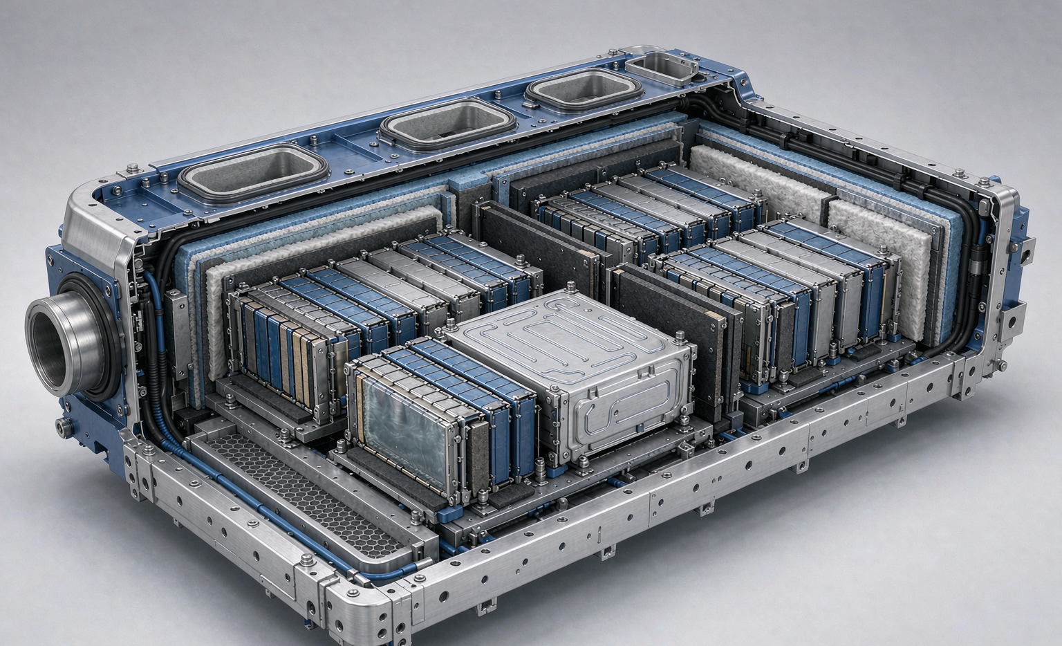
Our standard EV pack layout uses three defensive layers between cells and between modules. First, a mica sheet (0.3 to 0.5 mm) rated to withstand 800 to 1000 °C, placed on the cell-facing side because mica holds its integrity under direct flame. Second, a silica-aerogel pad (1 to 2 mm) with thermal conductivity below 0.05 W/m·K to throttle heat flux. Third, a ceramic-fibre or PCM (phase-change material) gap filler that absorbs the burst of energy during the first seconds of a fault.
Cooling is the other half. We default to liquid cold plates with a thermal interface gap-filler rated 2 to 5 W/m·K, holding cell-to-cell temperature spread under 5 °C across the module. In higher-power custom battery solution work — for example heavy-duty or track-grade packs — we have moved to direct immersion cooling, where the dielectric fluid also acts as a propagation buffer. The choice is driven by the customer’s continuous and peak C-rate, not by what looks neat on a slide.
Venting and pressure relief close the loop. Each module sits in an enclosure with a calibrated pressure-relief vent set between 0.5 and 1.5 bar, fitted with a flame-arresting membrane so that any ejected gas is cooled below its auto-ignition point before it leaves the pack. We size the vent area against the worst-case gas generation rate measured during the single-cell trigger test, and we route the exhaust away from the occupant compartment. The enclosure itself is sealed to IP67 and the internal atmosphere is monitored for vent-gas markers so the BMS can raise a pre-propagation alarm, not just a post-event one.
BMS and Early-Warning Strategy for Semi-Solid Packs
No barrier design is complete without a brain. Our pack BMS samples every cell’s voltage and at least two temperature points per module at 10 Hz or faster, and it tracks internal resistance drift to catch the early swelling or lithium-plating that precedes a hard fault. For semi-solid cells we tune the warning thresholds around the chemistry’s wider operating window — these cells stay stable further into the high-temperature band, so a naive LFP-style cutoff would either nuisance-trip or, worse, miss the real onset.
We also spec an insulation-monitoring device (IMD) on the high-voltage bus. At a 400 to 800 V pack, we require isolation resistance above 1 MΩ at 500 VDC and a ground-fault trip at 30 mA within 300 ms. These are not semi-solid-specific rules, but they matter more as pack voltage climbs, and they are part of every EV safety file we submit.
Beyond hard thresholds, we use impedance-based early warning. By comparing each cell’s DC internal resistance against its own baseline every charge cycle, the BMS can flag the slow divergence that precedes swelling or internal shorts days before a voltage or temperature trip would fire. In fleet programs we aggregate this telemetry so a marginal module is swapped during scheduled service rather than discovered during an abuse event. That predictive layer is where semi-solid packs, with their wider stable window, give us the most usable lead time.
Qualification Walkthrough: From Prototype to Production Pack
When a customer brings us a pack requirement, qualification follows a fixed sequence. We start with cell-level UN38.3 and IEC 62619, then build a 3 to 5 module pilot and run the propagation test under GB 38031 / ECE R100. Only after the pack passes do we move to the full enclosure, where we add vibration (simulating 8 to 15 years of road load), ingress protection (IP67 minimum for the pack shell), and the UL 2580 fire-exposure check. A clean run from prototype to production-qualified pack typically takes 10 to 16 weeks, dominated by the repeated propagation and calendar-aging cycles rather than by the chemistry itself.
The same engineering discipline transfers directly to other programs. The thermal-barrier and BMS principles we use for automotive packs are reused, scaled down, in our drone battery lines, where weight dominates but the runaway physics are identical. And when a client needs a non-automotive form factor, we deliver it as a custom battery solution with the same test matrix — the standards change by region, but the safety logic does not.
Frequently Asked Questions
How is a semi-solid battery safer than a normal lithium-ion EV pack?
The main gain is removing most of the free flammable solvent. That raises the thermal-runaway onset by roughly 30 to 50 °C and eliminates the ignitable electrolyte mist that drives fast propagation, giving the pack’s barriers more time to contain a single-cell fault.
What standard certifies an EV battery pack for road use?
There is no single global certificate. We qualify to UN38.3 for transport, IEC 62619 for the cells, GB 38031 and ECE R100 for vehicle propulsion packs, and UL 2580 for the North American market. A production pack must clear the relevant set for its sales region.
Can semi-solid cells still catch fire?
Yes. Any high-energy lithium chemistry can release energy under severe abuse. “Safer” means a wider margin and slower propagation, not immunity. The pack design — barriers, venting and BMS — is what converts that margin into a survivable event.
Do these safety methods apply to drone battery packs?
The runaway physics are the same, so the barrier and monitoring logic carries over. The difference is that a drone battery is weight-constrained, so we use thinner barriers and rely more on cell-level margins and aggressive BMS cutoff than on heavy pack-scale insulation.
How long does pack safety qualification take?
For a new EV pack, a clean qualification from prototype to production-ready typically runs 10 to 16 weeks, with most of that time spent on repeated thermal-propagation testing and calendar-aging validation rather than on initial cell screening.