Lithium Battery Testing for Power Tools: A Factory
I have lost count of how many tool packs I have torn down that looked perfect on paper and failed the first time a real current profile hit them. After twelve years turning cells into packs, my conviction is simple: a lithium battery is only as good as the test plan that proved it. For power tools, that bar is high. A drone pack flies under controlled conditions; a tool pack gets hammered by 100 A impact pulses, dropped off scaffolding, frozen overnight in a truck, and charged in the sun. If your lithium battery testing for power tools stops at a capacity check on the bench, you are shipping blind.
Below is the validation protocol my team runs on every high-drain tool pack before it earns a production release. It covers cell intake, pack functional test, abuse qualification, environmental stress screening, BMS verification, and the end-of-line gate that keeps bad units out of the field. These are the same numbers and standards we hold ourselves to whether we are building a 5S2P slide-on pack or a custom battery solution for an OEM platform.
Why Power Tool Packs Need a Testing Discipline of Their Own
The reason tool packs break differently from every other consumer lithium battery is the load signature. A typical jobsite tool draws repetitive high-current pulses: an impact wrench spikes 60–120 A for 30–200 ms, a circular saw holds 40–60 A for seconds, and a stalled drill can hit 90 A in under a second. That signature is simultaneously a DCIR problem, a thermal problem, and a mechanical-weld-fatigue problem, and a single test cannot cover all three.
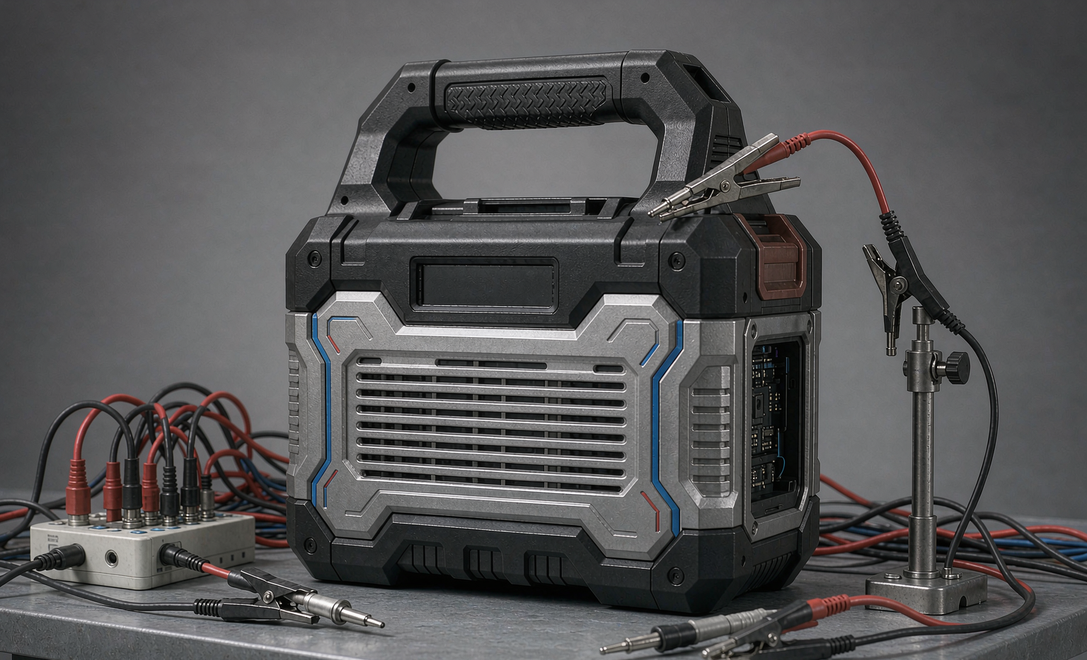
So my first rule of lithium battery testing for power tools is that you test against the measured current profile, not the nameplate. Before a pack is released we capture at least ten real work cycles on the actual tool with a current shunt and a scope logging at 10 kHz or faster, then we design the test plan around three numbers pulled from that trace: peak current with duration, sustained current with duration, and energy per charge under the customer’s duty. Everything downstream is graded against those three.
Incoming Cell QA: Where Every Good Pack Starts
A pack is only as consistent as the cells that go into it, and cell-to-cell spread is the enemy of both performance and life. Our intake test on every lot is deliberately aggressive because a bad lot caught at intake costs cents; caught in the field it costs a recall.
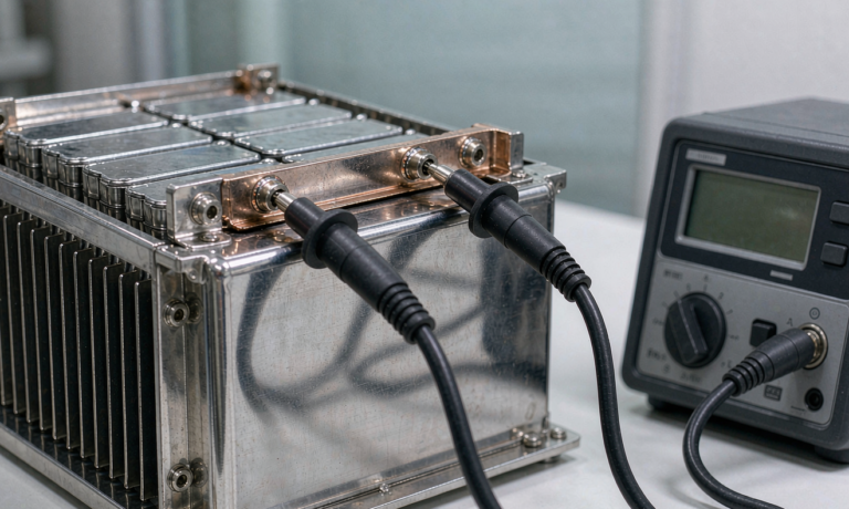
- DC internal resistance by 4-wire Kelvin: I reject any lot whose cell DCIR spreads more than 10% within the batch, and for parallel strings I want cells matched within 3–5% on capacity and under 10% on DCIR from the same lot. Mismatched parallel cells share current unevenly and the low-resistance cell ages first.
- Capacity grading: full constant-current discharge at the rated rate, binned so the coefficient of variation stays below 6%. This single step is what keeps end-of-discharge voltage spread tight across a pack.
- AC impedance and pulse capability: an ACIR sweep catches hidden separator defects a capacity check misses, and a short high-rate pulse verifies the cell actually delivers its rated continuous current without excessive sag.
- Cold-corner verification: I grade a sample at −10 C, not just 25 C. Cold performance is where warranty claims come from, so the acceptance limit is set at the cold corner.
Every accepted lot gets a retained reference cell sealed in the genealogy record. When a field failure appears six months later, I can pull the twin of that exact cell and re-run it.
Pack Functional Test: Proving It Delivers Under Load
Once assembled, the pack runs a functional test that mimics the tool, not a textbook. A constant-current 1C discharge tells you almost nothing about a tool pack; the real test is the pulsed profile.
- Pulsed discharge profile: we replay the captured current trace — the 60–120 A impact pulses, the sustained saw cuts, the stall events — and measure pack terminal voltage at the worst pulse. Acceptance is a sag limit, not a capacity number.
- Voltage sag acceptance: for an 18 V class pack I hold the stack above the tool’s undervoltage lockout, typically 15 V, even at the deepest low-temperature, low-state-of-charge pulse. If a pack sags through the lockout on the simulated stall, it fails regardless of its milliamp-hour rating.
- Capacity verification: a full discharge at the rated rate confirms the cell count and weld integrity. A pack reading low capacity almost always has a poor weld or a misoriented cell.
- Thermal read during load: the center cells are instrumented and the surface temperature rise under the pulsed profile is recorded. A pack that overheats under its own duty cycle fails the thermal acceptance even if it survives electrically.
This is also where I confirm a lithium battery pack built on a custom battery solution actually meets the runtime the OEM quoted. Runtime is a promise; the pulsed functional test is how we keep it.
Abuse and Safety Qualification: UN38.3, IEC 62133-2 and Beyond
Functional testing proves the pack works. Abuse testing proves it fails safely. For a tool pack that travels in a truck, a toolbox and an aircraft hold, the qualification dossier is non-negotiable.
- UN 38.3, tests T.1–T.8: altitude, thermal cycling, vibration, shock, external short circuit, impact and crush, overcharge and forced discharge. This sequence is required to legally transport lithium batteries by any mode and must be planned early because it is destructive and consumes dedicated samples.
- IEC 62133-2: the safety requirements for portable sealed secondary lithium cells and batteries, covering the internal short-circuit, overcharge and temperature abuse tests that govern cell-level safety.
- IEC 62619: the industrial battery safety standard we apply for any pack that ships into professional or stationary-adjacent use, because its thermal runaway propagation requirements are stricter than the consumer baseline.
- UL 2580 and regional marks: for North American market access we validate to the relevant cell and pack safety standards and retain the reports.
- Internal abuse screens: nail penetration and crush-to-failure on sample cells, watched for propagation. A single cell failing is acceptable; a cell failing and taking its neighbors with it is not.
I treat these certificates as a floor, not a finish line. A pack that passes UN 38.3 and then fades to 70% in 300 jobsite cycles has still failed the customer, so qualification always runs alongside cycle-life validation at the real duty profile.
Environmental Stress Screening: Thermal, Shock and Ingress
The field is colder, hotter, wetter and rougher than any lab, so we screen for it on purpose. Environmental stress screening is about finding the weak pack before the customer does.
- Thermal chamber cycling: operate the pack from −10 C to 60 C, charging only in the safe window (no charge below 0 C, none above roughly 45 C). We watch for capacity collapse, BMS lockouts and NTC drift across the range.
- Mechanical shock and vibration: we hold to MIL-STD-810H method 516.8 for shock and 514.8 for vibration, and beyond the standard we drop the pack 2 m onto concrete across all six faces and four corners because that is what a pack falling from a ladder actually experiences. Marginal welds and unretained sense wires are exactly what this test exposes.
- Ingress protection: IP54 as a floor, IP65 where the platform calls for it, verified per IEC 60529 with a tolerance-stack analysis on the gasket rather than a hopeful assumption. We also confirm that cell pressure-relief vents do not become water paths.
- Insertion-cycle test: the slide-on terminal is mated and separated 5,000–10,000 times and contact resistance is re-measured; rising resistance here shows up in the field as lost power and a hot terminal.
BMS Functional Test: Verifying the Guardian
The protection circuit is the only thing standing between a fault and a fire, so it gets its own test pass rather than a glance. Off-the-shelf modules tuned for laptops nuisance-trip on tools, and a tool BMS has to tell a legitimate 100 A stall pulse from a genuine short.
- Layered overcurrent: a microsecond short-circuit trip plus a slower overcurrent threshold set above the tool’s worst legitimate stall, with a deliberate 100–500 ms blanking window so normal inrush and impact pulses pass.
- Pre-charge and contactor logic: verified so the pack does not arc the tool’s input capacitors on insertion.
- Fuel-gauge accuracy: the coulomb count is checked against the measured discharge over a full cycle; a gauge that lies by 20% trains users to deep-discharge the pack and kills cycle life.
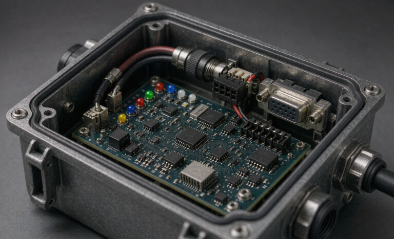
- Balancing and per-cell monitoring: every cell group voltage is read and passive balancing is confirmed to hold spread inside spec. Pack-level-only protection cannot see a single weak cell, and a single weak cell precedes a field failure.
- Non-volatile fault log: peak temperature and fault counters are written to memory. On a warranty return that history is the difference between root cause and guesswork.
End-of-Line Gate and the Fleet Feedback Loop
The plan is worthless if bad units ship, so every pack passes an end-of-line gate before it leaves the building, and the data from that gate feeds the next design iteration.
- Burn-in acceptance: a percentage of packs run a full pulsed burn-in and the line is held to a first-pass yield gate of 98% or better. Below that, the build stops and we find out why.
- Genealogy by DataMatrix: each pack carries a 2D code linking cell lot, weld parameters, BMS firmware and test results to its serial number. When a vendor ships a bad lot, traceability is the difference between a targeted field action and a blanket recall.
- Field-return teardown: every returned pack is opened, photographed and its fault log read. The recurring failure modes — sense-wire fatigue, terminal resistance creep, center-cell hot spots — go straight back into the test plan so the next lot is screened for them.
- Continuous validation: as a lithium battery manufacturer we re-run a condensed version of the full plan on a rolling sample of production output, not just on the prototype. Certificates age; packs do not.
This closed loop is why a custom battery solution outperforms an adapted stock pack over time. The test data belongs to your product, so the improvements compound instead of wandering.
The Standards Floor I Hold Every Pack To
For any power-tool lithium battery leaving our line, the minimum dossier is UN 38.3 T.1–T.8, IEC 62133-2, IEC 62619 and the relevant regional safety marks, plus design-verification cycle life holding 80% capacity at 500 cycles under the customer’s real duty profile. A drone battery pack we build for aerial work faces the same internal cell tests but a different transport and abuse envelope, and we qualify it to the same internal-resistance and abuse floor before it flies. Holding one consistent safety baseline across chemistries — NMC, LFP and even semi-solid — is what lets an engineering team scale without relearning failure modes for every new product.
Frequently Asked Questions
What tests are required for a power tool lithium battery?
At minimum, UN 38.3 T.1–T.8 for transport, IEC 62133-2 for cell and pack safety, and a functional pulsed-discharge test that proves the pack holds voltage under the tool’s real current profile. For professional and industrial use we add IEC 62619, and for North America the relevant UL safety marks. Capacity-only checks are not sufficient on their own.
How do you test a battery pack for high current pulses?
We replay the measured tool current trace — impact pulses, saw cuts, stall events — on a programmable load and record pack terminal voltage at the worst pulse. The acceptance criterion is a sag limit that keeps the stack above the tool’s undervoltage lockout even at low temperature and low state of charge, not a simple milliamp-hour number.
Why measure DC internal resistance with a 4-wire Kelvin method?
A 2-wire measurement folds the lead and contact resistance into the result, which on a low-resistance cell like a high-drain 21700 can be a large fraction of the true value. The 4-wire Kelvin method separates the sense path from the current path, so the number you grade cells by is the cell’s own resistance, which is what actually decides voltage sag and heating.
How many charge cycles should a tool battery last?
For a well-built high-drain pack on a matched cell lot, we design-verify to 80% capacity retention at 500 cycles minimum under the real duty profile, and LFP-based packs routinely exceed 2,000 cycles. The number only holds if the pack passes the pulsed functional test and the BMS keeps cell balance within spec across its life.
Does a power tool battery need UN38.3 certification?
Yes. UN 38.3 is required to legally transport lithium batteries by air, sea or road, whether the pack ships alone, with a tool, or inside equipment. Because the T.1–T.8 sequence is destructive, it must be planned into the build schedule with dedicated samples rather than bolted on at the end.
Can a custom battery solution be tested faster than a stock pack?
Not faster, but cleaner. Because the cell choice, holder, BMS thresholds and terminals are all developed against one tool’s measured profile, the test plan maps directly onto the design intent, so fewer iterations are wasted proving a pack against a use case it was never shaped for. The total qualification time is similar, but the result fits the tool.
Closing Thought From the Bench
The packs that come back from the field are almost never the ones that failed a capacity check. They are the ones that passed a weak test plan. My rule is to test the pack the way the tool will actually use it, qualify it the way it will actually travel and fail, and close the loop with every return. Do that, and lithium battery testing for power tools stops being a checkbox and becomes the reason the pack lasts.