Lithium Battery Safety for UPS Systems
I have spent more than a decade around battery rooms, and lithium battery safety for UPS duty is the subject where I see the largest gap between what a datasheet promises and what actually protects a facility. A UPS battery is a strange animal: it sits at 100% state of charge for months, does nothing, and then in one morning it has to deliver a three-minute, 2C discharge that keeps an operating theatre, a trading floor, or a semiconductor fab alive. Nothing else in the lithium world behaves like that. Traction batteries cycle; solar batteries cycle; a UPS battery mostly waits and ages. That duty profile creates a very specific set of hazards, and almost all of them are underestimated at specification stage.
This article is the safety chapter of my UPS series. I have already covered what to specify for performance, how to model reliability, where the cost really sits, how a battery pack design is engineered for UPS strings, which test regime separates a real product from a brochure, and what separates a qualified lithium battery manufacturer from an assembler. Here I want to talk about the part that matters when everything else has already gone wrong: preventing a lithium battery in a UPS room from injuring someone, destroying a data hall, or silently losing capacity until the day the grid drops.
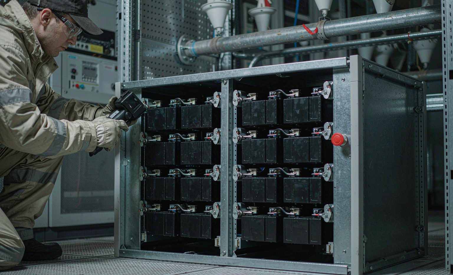
Why UPS Duty Is a Different Safety Problem Than Motive or Storage Duty
When engineers move into the UPS world from electric vehicles or solar storage, they carry habits that do not transfer. Three differences dominate the safety picture.
Float service, not cycle service
A lithium battery pack built as a custom battery solution for a specific UPS spends 99% of its life sitting at the top of its voltage window, held there by a float charger. Calendar ageing, not cycle ageing, governs its life, and calendar ageing is brutally temperature-sensitive: as a rule of thumb I use in every design review, every +10 K above 25 °C roughly doubles the rate of capacity loss and internal-resistance growth. A VRLA room that was “fine” at 30 °C will eat a lithium battery’s calendar life roughly 40% faster than the same room at 20 °C. But the safety consequence is subtler than the financial one: a pack that has aged by SEI growth and lithium plating carries more internal resistance and more heterogeneity between cells, and heterogeneity is what pushes a weak cell out of its safe operating area during a high-rate discharge.
Discharge rates the chemistry must survive cold
UPS autonomy is short by design — 3, 5, 10 or 15 minutes at full load. On a 10-minute rate that is roughly a 2C to 3C discharge at the pack level, sometimes 4C for high-power modules. A cell that happily qualifies on a 0.5C cycle-life test can be driven past its safe internal temperature during a 3C pulse at 40 °C ambient, particularly late in life when DCIR has grown. I have reviewed strings where the end-of-life DCIR was 1.6× beginning-of-life and the resulting I²R heating during a 10-minute discharge added 18 K to the cell core temperature. That margin must be built into the design, not discovered during a commissioning test.
The retrofit trap
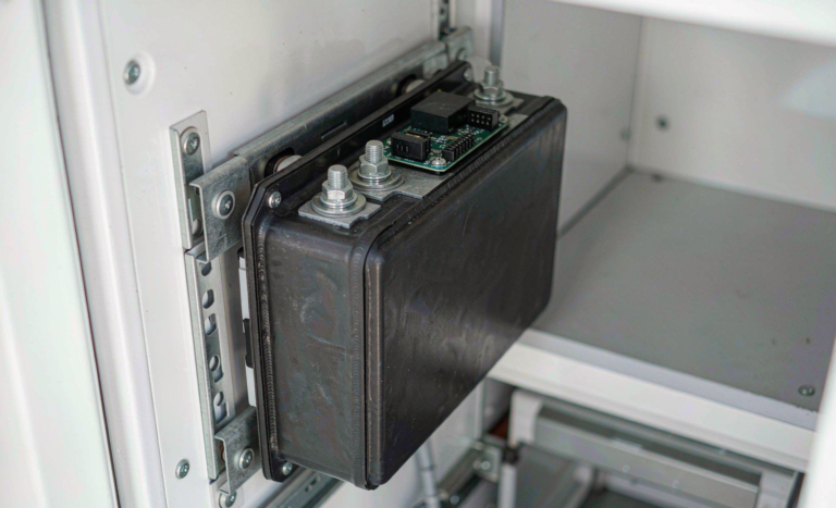
Most lithium UPS projects are not greenfield. They are a VRLA-to-lithium retrofit inside an existing room, often on an existing UPS. That is where the worst safety errors live, because the legacy charger, the legacy inverter low-voltage cutoff, the legacy DC protection, and the legacy room clearances were all sized for a battery technology with roughly ten times the internal resistance and a completely different voltage curve.
Chemistry Selection Is the First Safety Decision
I am not going to pretend this is a close call for stationary UPS. Lithium iron phosphate (LFP) is the correct default, and I specify it unless there is a floor-loading or footprint constraint that makes NMC the only option.
The reason is the thermal hierarchy. In accelerating rate calorimetry that I have run with cell suppliers, LFP cells typically show self-heating onset around 180–210 °C, with thermal runaway triggering above roughly 250 °C. NMC (particularly high-nickel 811) can begin self-heating at 120–150 °C and go into runaway at 180–200 °C, and — the important part — it releases oxygen from the cathode as it decomposes. Once a cell chemistry supplies its own oxidiser, no quantity of clean-agent gas suppression in the room will stop it. LFP’s olivine phosphate bond is far more robust; the cell still fails energetically if abused, but the window between “something is wrong” and “irreversible” is materially wider, which is exactly what a monitoring system and an emergency plan need.
The second reason is the separator system. Standard polyolefin separators close their pores around 130–140 °C (polyethylene) and melt around 165 °C (polypropylene). Ceramic-coated separators push dimensional stability past 200 °C. For a UPS room where a single event can cost more than the entire battery, I specify ceramic-coated separators and a cell-level current interrupt device and vent, and I ask the manufacturer for the UL 9540A or IEC 62619 cell-level propagation data rather than accepting a statement that the pack is “safe”.
Float Voltage, End-of-Discharge Voltage, and the Retrofit Voltage Trap
Here is the single most common technical failure I find in VRLA-to-lithium UPS retrofits, and it is a safety issue as much as a life issue.
A legacy 48 V VRLA string is 24 cells, floated at roughly 2.25–2.30 V per cell, i.e. about 54.0–55.2 V at the terminals; boost/equalise can reach 2.40 V per cell (57.6 V). Now consider the two common LFP configurations:
- 16S LFP — nominal 51.2 V, float at 3.40–3.45 V/cell = 54.4–55.2 V, maximum 3.65 V/cell = 58.4 V.
- 15S LFP — nominal 48.0 V, float at 3.40–3.45 V/cell = 51.0–51.8 V, maximum 3.65 V/cell = 54.75 V.
A 16S pack dropped onto a charger that floats at 54.4–55.2 V is acceptable — that is 3.40–3.45 V/cell, right where you want it. The same pack on an “equalise” cycle at 57.6 V, however, is 3.60 V/cell, and a charger with temperature compensation designed for lead-acid (typically −3 to −5 mV/°C/cell, i.e. −72 to −120 mV/°C on a 24-cell string) will push higher voltage in cold rooms. That is how lithium packs get cooked in winter. A 15S pack on the same legacy float is worse: 54.4 V across 15 cells is 3.63 V/cell, essentially sitting at full charge permanently, which maximises calendar ageing and, if the BMS balance circuit is weak, drives the strongest cells into overvoltage.
Rule I apply without exception: the charger profile must be reconfigured for the lithium pack, temperature compensation must follow the lithium coefficient (roughly −3 mV/°C/cell for LFP, with charge inhibited below 0 °C and restored around +5 °C, current de-rated to 0.2–0.5C between 0 and 15 °C), and equalisation must be disabled. If the existing UPS cannot be reprogrammed, the correct answer is a new charger, not a compromise.
The mirror-image problem sits at the bottom of the window. A legacy UPS inverter typically ends discharge around 1.67–1.75 V per VRLA cell, i.e. 40–42 V on a 48 V string. An LFP cell should not be taken below about 2.5–2.7 V. On a 16S pack that is 40.0–43.2 V, which happens to be tolerable; on a 15S pack it is 37.5–40.5 V, which is not. If the inverter cutoff is not raised to match, you either lose usable capacity or you abuse the cells — and a cell driven into copper dissolution and re-plating at end of discharge is a latent internal-short risk. This is a two-minute setting change with a decade-long consequence.
Short-Circuit Current, Protection Devices, and the Arc-Flash Reality
Every safety conversation about lithium in a UPS eventually arrives at fault current, and it usually arrives too late.
Lead-acid has generous internal resistance. A large VRLA string might deliver a few thousand amps into a bolted fault. A lithium pack of the same nominal voltage and capacity, with a pack-level DCIR of 2–5 mΩ, will deliver on the order of 10,000 to 25,000 A into the same fault on a 48 V system. Large three-phase UPS battery strings are worse: a 512 V LFP rack (160S) with 20–40 mΩ pack resistance still yields 13–25 kA prospective, and the DC arc from a source of that magnitude is a genuinely different hazard class from the one the facility’s electrical safety program was built around.
Three consequences follow:
- Protection devices must be re-rated for interrupting capability, not just continuous current. I specify DC-rated fuses or DC breakers with a verified DC interrupting rating at the system voltage — for IEC world, gG/gM or semiconductor aR/gR fuses per IEC 60269 with a DC rating; for North America, UL 248-recognised fuses with the DC voltage rating printed on the body. A 480 V AC-rated breaker used on a 512 V DC string is not a design, it is a wish.
- Sizing must remain selective. I size continuous-rated protection at 125% of maximum continuous current (156% where the load is continuous in the NEC sense), then verify selective coordination by comparing I²t: the downstream device must clear before the upstream device reaches its melt threshold across the full fault range, including the battery’s contribution and the rectifier’s contribution acting together.
- Physical placement matters. I put the main battery disconnect and the fuse as close to the battery terminals as mechanically possible — ideally within 150–200 mm of the terminal — because the cable between the cell and the protective device is unprotected cable, and a chafed run against a rack edge is the most common origin of a battery-room fire I have investigated.
On personnel safety: do the incident-energy study and label the equipment. AC arc-flash work follows IEEE 1584; DC arc-flash has no universally adopted standard method, but the NFPA 70E guidance and the published DC energy models are adequate for producing conservative PPE categories. What I insist on regardless of the calculation:
- A clearly identified DC service disconnect within reach of the rack, with a lockable handle.
- Written lock-out/tag-out procedure specific to the battery room, including the step people forget: verify zero energy at the pack terminals, not at the UPS display. A maintenance bypass does not de-energise the DC bus.
- Insulated tools rated to 1000 V (IEC 60900) and gloves appropriate to the voltage class, inspected on schedule.
- A two-person rule for any live work above 60 V DC — which, per IEC 61140 and the voltage bands in IEC 60449, is where DC becomes a genuine shock hazard rather than a contact hazard.
Thermal Runaway Propagation and Cabinet-Level Containment
A UPS battery room is a dense array of energetic modules in a shared enclosure, usually in an occupied building, often below or adjacent to the load it protects. That is precisely the scenario the propagation standards exist for.
UL 9540A is the test method I ask for, run at the level that matters. Cell-level data tells me whether the chemistry is sane. Module-level data tells me whether the mechanical design stops propagation. Unit- and installation-level data is what the authority having jurisdiction wants, and it is what determines spacing and suppression requirements. IEC 62619 covers the cell and block safety requirements for industrial applications including stationary storage, including the thermal abuse and internal short tests, and IEC 62485-5 is the installation-side safety standard for stationary lithium batteries — ventilation, protection, clearances, and labelling. IEC 62040-1 governs the UPS itself, including the battery circuit and the safety interlocks.
In practice I require the following at module and rack level:
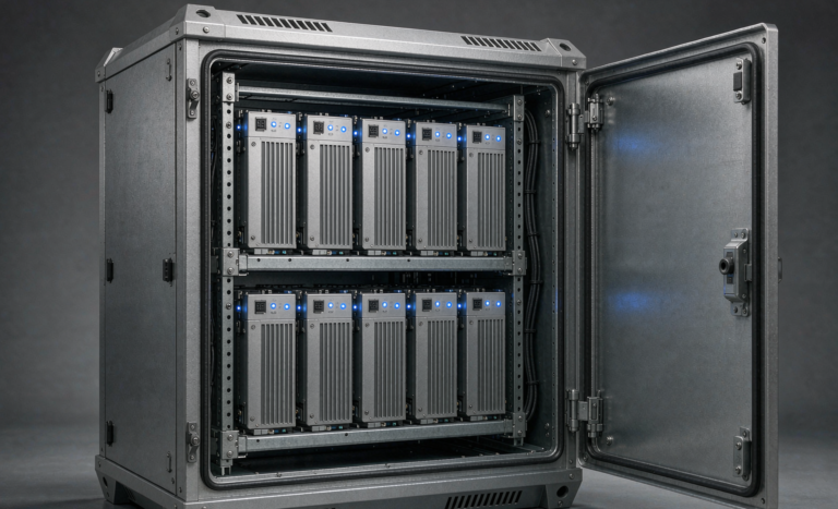
- Cell-level venting directed away from adjacent cells, with a defined exhaust path out of the module rather than into it. Vent gas from a failing LFP cell is flammable and contains hydrogen fluoride; the plumbing design matters as much as the cell.
- Thermal barriers between modules — intumescent or ceramic fibre — verified by test data, not by assertion.
- Per-module temperature sensing with the sensor on the cell or busbar, not floating in the cabinet air. Air temperature lags the cell by tens of seconds during a 3C discharge and by minutes during a slow internal short.
- A rate-of-rise as well as absolute threshold. A cell climbing at more than about 1 °C/min with no load current is an alarm condition in my book, regardless of the absolute value.
Room Level: Detection, Suppression, Ventilation, and Code
This is where I most often have to correct a client’s consultant.
Clean agent does not extinguish a lithium battery fire. HFC-227ea, FK-5-1-12, and inert gas systems work by displacing oxygen or interrupting the chemical chain reaction of a fire that needs the room’s air. A cell in thermal runaway is generating its own oxygen and heat internally. Gas suppression will knock down flames from burning cable insulation and plastics — worth having, because that is how a battery incident spreads to the building — but it will not cool the cells or stop propagation. The only practical agent that removes heat from a battery mass is water, and a great deal of it, applied by sprinkler, water mist (NFPA 750), or a fire-service hose stream. My standard position: provide code-required sprinkler or water-mist coverage in lithium battery rooms, and design the drainage and the water-supply duration for the incident, not for the room’s ordinary fire load.
Detection should be staged, and early. Smoke is a late indicator. I specify very-early-warning aspirating detection (VESDA class) on the room, plus off-gas detection — carbon monoxide, hydrogen, and volatile organic compounds — inside the cabinets, wired to the BMS so that a venting cell trips the contactor and stops charge/discharge before there is anything to burn. Carbon monoxide typically rises measurably tens of minutes before smoke appears in a lithium incident; that window is the entire value of a monitoring system.
Ventilation and deflagration. Vent gas accumulates. Design to the applicable standard — NFPA 69 for explosion prevention by dilution, NFPA 68 for deflagration venting where the enclosure design requires it — with the calculation based on the manufacturer’s measured vent-gas composition and volume, not on a generic number. A 40 kWh LFP rack can produce tens of cubic metres of gas during a full propagation event; that is a room-scale problem.
Code anchors. In North America, NFPA 855 (Installation of Stationary Energy Storage Systems) drives most of what the AHJ will check: separated rooms or fire-rated construction above the applicable capacity threshold, unit spacing, separation from exits and hazardous materials, signage, and a thermal management and ventilation design. NFPA 72 for detection and signalling, NFPA 70 / NEC Article 480 (and Article 706 in the 2020 cycle, relocated in later cycles) for the storage battery installation, NFPA 75 for information-technology equipment protection, and NFPA 1 / IFC 1207 where adopted. Product listings: UL 1973 for stationary batteries, UL 9540 for the system, UL 9540A as the propagation evidence. Internationally, IEC 62485-5, IEC 62619, IEC 62040-1/-2/-3, and IEC 63056 for the battery’s safety in the system context.
Commissioning, Monitoring, and the Discipline of Trending
Safety in year five is decided by what you measure in week one. My commissioning acceptance file for a lithium UPS includes:
- Cell voltage spread at rest: a healthy new pack sits within roughly 30 mV across all cells; I set the warn threshold at 50 mV and the fault threshold at 100–150 mV depending on the format. A pack delivered with 80 mV of spread is a quality problem, and I reject it before it is energised.
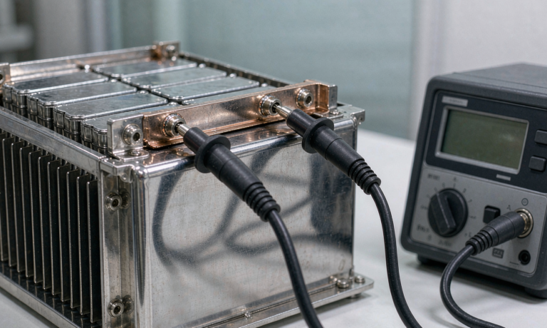
- Insulation resistance: measured at the string voltage or with a 500 V insulation tester, with a floor of 100 Ω per volt of nominal system voltage per IEC 62485 practice. A healthy new string measures in the tens of megohms; anything in the hundreds of kilohms gets investigated.
- Termination torque: recorded per bolt, 100% torque-marked, with a documented re-torque at 50 operating hours and then at the annual service. I size copper to a 3% voltage drop on the main path and 1% on sense leads, and I check every lug with an infrared scan under load.
- Infrared thermography under a real discharge. A 20 K rise over the coolest comparable joint is my investigation threshold; 30 K is a stop-work threshold. Do this during the load-bank test, not during a float period when nothing is heating.
- BMS alarm injection. Verify that every protective function actually opens the contactor: overvoltage, undervoltage, overcurrent, over-temperature, insulation fault, and communication loss. A BMS whose protection was never end-to-end tested is a monitoring device, not a protection system.
After commissioning, the trending that matters is DCIR growth and capacity drift. I take a full capacity test annually (or a validated partial test with the manufacturer’s correlation), and I plot per-module DCIR. My retirement criteria are the ones I apply across every lithium program: capacity below 80% of nameplate, DCIR above roughly 1.3× beginning-of-life, or a static cell-voltage spread beyond 50 mV that will not balance out. A module that meets any one of these is removed from service, not “monitored more closely” — in a UPS, a module that cannot deliver its share of a 3C discharge places an overcurrent burden on its neighbours at the exact moment the facility has no margin.
Spare Strategy and End-of-Life Handling
Two practical points that get skipped and then cost a great deal of money.
Spares need a state-of-charge policy. I hold spare modules at 30–50% SoC in a temperature-controlled store, with a six-month top-up and check. Holding spares at 100% in a warm store is the fastest way to add two years of calendar ageing to a part that may sit for three. A spare pool of roughly 3–5% of installed modules has been the right number for the sites I support, weighted toward the module types with the longest lead time.
Removal is a transport event. A module leaving a UPS room is dangerous goods. It must be discharged or verified to no more than 30% state of charge, terminals insulated, and packed and documented under UN 38.3 (the full T1–T8 test series evidence for the cell and pack design) and shipped as UN3480 — or UN3481 if it ships with equipment — under the IATA Dangerous Goods Regulations or the applicable modal code. In the EU, the battery regulation (EU) 2023/1542 phases in the battery passport from 18 February 2027, and the end-of-life producer-responsibility and material-recovery obligations are not optional. For stationary storage in China, GB/T 36276 remains the reference for the lithium-ion battery product itself.
Frequently Asked Questions
Is a lithium battery actually safe inside an occupied data centre?
Yes, when the chemistry, the listing, the room, and the maintenance discipline are all correct — and this is now the mainstream configuration in new builds for exactly that reason. LFP with ceramic-coated separators, a UL 9540 / UL 1973 listed system with UL 9540A propagation data, off-gas and aspirating detection, water-based suppression, and a room designed to NFPA 855 gives a hazard profile that is comparable to or better than legacy VRLA once you account for VRLA’s own hydrogen and thermal history. What is not safe is a lithium pack dropped into a VRLA electrical environment with the original charger profile, the original AC-rated protection, and no change to the room.
Can I drop lithium modules straight into my existing VRLA UPS?
Sometimes, but only after four checks. One: can the charger be reconfigured to the lithium float voltage, with lead-acid temperature compensation and equalisation disabled? Two: can the inverter’s end-of-discharge cutoff be raised to the lithium floor? Three: do the existing DC protection devices have an interrupting rating adequate for the lithium fault current, which can be five to ten times the VRLA value? Four: does the BMS have a dry-contact or protocol interface the UPS can act on for shutdown and alarm? If any answer is no, you need a component change, not an exception.
What autonomy should I specify with lithium?
Do not shorten autonomy simply because lithium tolerates higher rates. The safety case for shortening a 15-minute VRLA string to a 5-minute lithium string rests on the assumption that your generator starts in five minutes, every time. In my experience with real sites, a 10-minute lithium string gives most facilities a better reliability-per-dollar point than five minutes, because it absorbs generator start failures without pushing cells to a 4–5C rate. Whatever you choose, size the pack so the end-of-life DCIR case still delivers the load at a temperature the cells can survive.
What actually stops thermal runaway propagation?
Three layers, in order of effectiveness: cell selection and quality control (the best outcome is a cell that never enters runaway), thermal barriers plus directed venting at module level (so a single cell failure does not cook its neighbours), and active response (BMS opens the contactor on rate-of-rise, off-gas detection trips before smoke, suppression cools the mass). Gas suppression is not on that list as a propagation control — it is a building protection measure.
Does float charging damage lithium batteries?
Holding any lithium cell at 100% SoC and elevated temperature accelerates calendar ageing, so I do not pretend float is free. But UPS duty requires readiness, and the engineering answer is to float at the bottom of the acceptable window — roughly 3.40 V per cell for LFP rather than 3.65 V — keep the room at 20–25 °C, and disable equalisation. That combination typically delivers 10–15 years of float service from LFP, which is the number I underwrite in a specification.
What monitoring does the BMS need for a UPS?
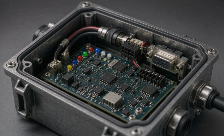
Per-cell voltage, at least two temperature points per module with the sensor on the cell or busbar, string current, contactor status and weld detection, insulation resistance to ground, and a communications path to the site DCIM or BMS by Modbus TCP or SNMP. The critical requirement is not the measurement — it is the action: a properly engineered BMS solution must have hardwired authority to open the contactor independent of any software, and that interlock must be proven during commissioning.
How often should a lithium UPS battery be capacity-tested?
Annually for the full string, with quarterly DCIR and cell-balance trending in between, and a thermographic survey during any real discharge event. If your internal policy is built around VRLA’s quarterly or monthly testing cadence, you are over-testing a lithium string to no benefit — lithium does not suffer the same sudden capacity cliff that a sulphated or dried-out VRLA jar does, and every unnecessary full discharge is cycle wear you paid for.
What is the single most common safety mistake you see?
Absent or re-used DC protection. Over and over I find lithium packs protected by devices selected for the VRLA fault current they replaced, or by an AC-rated breaker that has no verified DC interrupting capability. The pack can source five to ten times the fault current of the battery it replaced, and the device that is supposed to clear that fault simply cannot. Specify the interrupting rating at the system DC voltage before you specify anything else about the protection.