Lithium Battery Safety for Mobility Devices
I have spent more than a decade designing lithium battery packs, and the jobs that still keep me awake at night are not the ones with the biggest nameplate. They are the ones where a person is sitting on top of the pack. A powered wheelchair battery is typically 1.2 to 2.0 kWh — smaller than a home storage cabinet, smaller than a forklift pack — and it lives 200 to 400 mm from the hip of someone who, by definition, cannot walk away from it.
A few winters ago a distributor called me about a mobility scooter pack that vented in a hallway of an assisted-living building. Nobody was hurt. The fire service put it out with an extinguisher, the corridor was repainted, and the user was fine. But the detail that stuck with me was this: the user sat in the chair for the first ninety seconds because that is what you do when your legs do not work. In a drone, a thermal event costs you an airframe. In a mobility device, it costs the person their exit.
That difference changes almost every engineering judgement. This is the safety chapter of our mobility series — we have already covered lithium battery performance, reliability, cost optimisation, design, testing and manufacturing for mobility devices. Here I want to talk about the eight places where a lithium battery pack for a wheelchair or scooter goes wrong in the field, and the numbers I use to keep it from happening.
1. Why Mobility-Device Battery Safety Is a Different Problem
Every other application in our catalogue has one thing in common: when something goes wrong, there is a distance between the energy source and the human. A drone is overhead. A street light is four metres up. A forklift has an operator who can step down and run. A powerchair has a user strapped into a seat directly above, or beside, 1.28 kWh of stored chemical energy.
Four consequences follow from that, and they drive every decision in this article:
- Egress is not available. The user cannot self-evacuate quickly. Warning time — not just containment — becomes the primary safety function.
- The duty cycle is brutal. A daily chair user cycles 60–90% depth of discharge, 300–500 times a year. That is three to five times the cycle exposure of a typical standby application, and it compresses five years of calendar ageing into about three.
- The environment is unmanaged. The pack sees rain, puddles, kerb strikes at 8–12 km/h, ramp drops, shopping-centre heat, and unheated garages at −10 °C. There is no controlled room.
- It is a regulated device. In the United States a powered wheelchair is an FDA Class II medical device; in the European Union it falls under the Medical Device Regulation. The battery is not a consumer accessory bolted onto a product — it is a component of a regulated device, and the documentation burden follows.
That last point is the one that most retrofit suppliers miss. When a distributor sells a “universal 24 V lithium drop-in” into a chair that was type-approved with two AGM batteries, they have changed a regulated device. The paperwork — and the liability — does not follow the marketing.
2. Choose the Chemistry First: LFP Margins Versus NMC Energy Density
Almost every serious incident I have reviewed in mobility applications traces back to a chemistry decision made on a spreadsheet for energy density. So let us put the numbers on the table.
Lithium iron phosphate (LFP) runs 3.20 V nominal, with a 3.65 V maximum charge voltage and a 2.50 V end-of-discharge floor. NMC runs 3.60–3.70 V nominal, 4.20 V maximum, and 2.75–3.00 V minimum. At cell level NMC delivers roughly 200–260 Wh/kg against LFP’s 90–160 Wh/kg. That is a real, large advantage, and it is why NMC dominates consumer electronics.
Now the part that matters when a person is sitting on it. LFP cells typically show the onset of significant self-heating around 180–210 °C, with the main exothermic decomposition peak above 250 °C — often quoted in the 270–300 °C range — and critically, the olivine phosphate cathode does not release oxygen as it breaks down. NMC cells, particularly high-nickel formulations such as NMC 811, begin measurable self-heating nearer 120–150 °C and release oxygen from the cathode lattice as they decompose in the 180–220 °C band. That oxygen release is what turns a venting cell into a self-sustaining fire.
Layer on the separator behaviour that we all design to: polyethylene separator shutdown at roughly 130–140 °C, polypropylene melt nearer 165 °C, and ceramic-coated separators holding dimensional integrity past 200 °C. With LFP, the separator has already done its job well before the cathode becomes chemically aggressive. With high-nickel NMC, the two events are close enough that a hot cell can pass the separator’s capability while the cathode is still supplying oxidiser.
The voltage mapping is also kinder than people expect. An 8S LFP string gives 25.6 V nominal, 29.2 V at full charge and 20.0 V at end of discharge — squarely inside the window a 24 V AGM controller was designed for. A 7S NMC string gives 25.9 V nominal, 29.4 V full and 21.0 V empty, which also maps. So the “NMC is needed to fit the voltage” argument does not hold for 24 V mobility. The real difference is thermal margin, and I will take the margin every time.
There is a second, quieter safety argument. LFP delivers 3,000–6,000 cycles at 80% DoD against NMC’s typical 1,000–2,000. A chair that needs one LFP pack per five years instead of two NMC packs per five years has half the handling events, half the swap-outs done by untrained caregivers, and half the chances of a connector being forced in backwards at 11 pm. Fewer interventions is a safety feature.
The honest trade-off: LFP is roughly 30–40% larger for the same watt-hours. In a Group 24, NF22 or U1 tray that matters, and it is the reason some drop-in suppliers quietly reach for NMC. Our position as a lithium battery manufacturer is simple — if the LFP pack does not fit the tray, we redesign the tray or we build a custom enclosure. We do not shrink the margin.
3. The Lead-Acid Retrofit Trap: Chargers, Float and Equalisation Pulses
Here is the single most common failure I see in the field. A chair designed around two 12 V AGM or gel batteries in series gets a lithium drop-in, and the original charger stays. On paper the voltages look compatible. In practice they are not.
The typical 24 V mobility charger is a three-stage lead-acid unit at 5, 8, 10 or 12 A. It runs constant current into bulk, then constant voltage at 2.40–2.45 V per cell — 28.8–29.4 V on a 24 V pack — then drops to a float at 2.25–2.30 V per cell, 27.0–27.6 V. Most also apply temperature compensation at roughly −3 to −5 mV per °C per cell. Every one of those stages is optimised for lead chemistry, and each one interacts badly with lithium in its own way:
- Absorption is fine. 28.8–29.4 V on an 8S LFP string is 3.60–3.68 V per cell. That charges to roughly 97–100% SoC. No complaint, provided it terminates.
- Float is not. 27.0–27.6 V sustained is 3.38–3.45 V per cell, held indefinitely. Holding cells at high state of charge at 25–40 °C is the single largest accelerator of calendar ageing we have data for, and aged cells are the cells that grow dendrites. We spec the float-equivalent to 3.35–3.40 V per cell maximum, and we prefer chargers that simply switch off.
- Equalisation pulses are the dangerous one. Many lead-acid chargers periodically apply a desulfation or equalisation pulse at 2.58–2.67 V per cell — 31.0–32.0 V on a 24 V string. On 8S LFP that is 3.88–4.00 V per cell, well past the 3.65 V limit. The BMS must open the charge path to protect the cells. Depending on the charger, that either produces a confusing “no battery” fault or, worse, the charger keeps pulsing against an open protection switch and the pack latches into a permanent fault state.
- Temperature compensation is inverted risk. A lead-acid charger in a cold garage raises its output voltage, typically by 3–5 mV per °C per cell below 25 °C. LFP must not be charged at all below 0 °C. So the colder it gets, the harder the charger pushes into cells whose charge-transfer resistance has risen sharply. That is the textbook recipe for lithium plating — metallic lithium depositing on the anode instead of intercalating — which shows up weeks later as an internal short with no obvious external cause.
None of this is exotic. It is the ordinary, predictable consequence of plugging a lithium electrochemistry into a lead-acid charge algorithm. Our specification rule for any mobility custom battery solution is blunt: the charger ships with the pack, or the pack ships with a written, verified list of compatible chargers and explicit instructions to disable any equalisation stage.
The 3-Pin XLR and the Inhibit Loop
Two mechanical details catch almost every first retrofit. First, most powerchairs charge through a 3-pin XLR connector, and the third pin is commonly an inhibit or temperature-interlock loop. Many chargers simply will not start unless that loop is present. If the replacement pack does not reproduce it, the chair never charges and the user is stranded — and stranded users do unsafe things, like borrowing a charger from a different chair.
Second, if a BMS solution opens the pack on a protection event, the charger sees zero volts at the terminals. Most chargers treat that as a dead battery and refuse to start. A single legitimate over-temperature trip at 45 °C on a summer afternoon then leaves the user with a chair that will not charge even after it cools down. We either design a keep-alive wake path into the pack or we require a charger with explicit 0 V recovery. This is not a convenience feature; it is what keeps a protection event from becoming an abandonment.
4. Series BMS, Regenerative Braking and Opening the Circuit at the Wrong Moment
A “24 V lithium kit” sold as two 12.8 V drop-in batteries is, electrically, two independent BMS boards in series. That architecture has a specific failure mode that does not appear in a single-BMS design.
When one board opens on a protection trip, the full string voltage appears across the open MOSFET of the board that tripped — plus whatever transient the chair generates. In a 24 V nominal stack, a regenerative braking spike or an inductive kick from the motor can push that well past the drain-source ratings of the small MOSFETs used in compact drop-in boards. We have seen boards with a 100 V VDS rating driven into avalanche on a stack that is nominally 29 V. The result is a board that fails short, and a pack that is now unprotected.
The rule we build to: one BMS per string. Eight series cells, one sense harness, one charge and discharge path, one decision-maker. If a design requires two enclosures for mechanical reasons, they share a single control board.
Then there is regenerative braking, which is genuinely specific to mobility. Powerchair controllers run 50–120 A continuous with 150–200 A peaks, and most of them use regenerative braking to hold speed on a ramp. Regen current flows into the pack. If the BMS hard-opens the discharge path mid-regen, braking torque disappears instantly.
Now, the chair’s electromechanical brakes are fail-safe — spring-applied, power-released — so the chair will stop. But it stops in a way the user did not choose, on a slope, with a high centre of gravity and a seated occupant. In our own risk assessment that is a tip hazard, and it ranks above the cell protection that caused it.
The cold-and-full case makes it worse. Charging below 0 °C is inhibited, so a chair descending a ramp at −5 °C with a 100% pack pushes regen current into cold cells with high charge-transfer resistance. Pack voltage spikes past the over-voltage threshold, the BMS opens to protect the cells, and the braking goes with it.
How we resolve it:
- Never hard-open the regen path. Clamp instead. Set a temperature-dependent regen acceptance limit — 0.1–0.2 C below 0 °C, up to 0.5 C between 5 and 15 °C, full acceptance above 15 °C — and dump the excess into a braking resistor through the controller when the pack cannot take it.
- Two-stage over-voltage. A pack-level OV trip at 3.75–3.80 V per cell with a 1–2 second delay, so a short regen spike does not trip it, backed by an undelayed cell-level hard OV at 3.90 V per cell as the last line.
- Keep the controller alive. Brake and logic supply come from a separate fused tap ahead of the BMS, so a protection trip cannot drop the control rail.
- Precharge, always. Controller input capacitance is typically 5,000–20,000 µF. Connect a hot pack directly and you weld the main contactor or fuse the protection MOSFETs on the first plug-in. Precharge through 20–50 Ω to 90% in one to three seconds.
5. Mechanical Retention, Crash Loads and Ingress
There are two loading cases that a mobility pack must survive, and they are completely different.
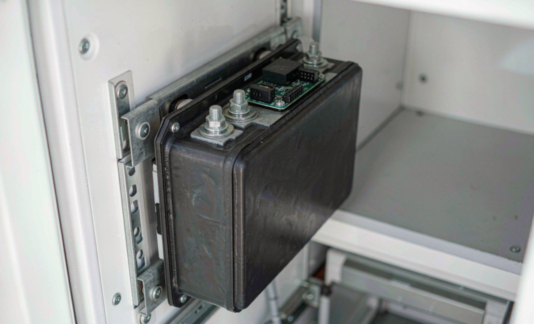
The first is transport. ISO 7176-19 — harmonised in the US as ANSI/RESNA WC-4 — covers wheeled mobility devices used as seats in motor vehicles, and it uses a frontal sled deceleration pulse of 20 g. A 15 kg pack under 20 g generates roughly 2.9 kN of inertial load. That is not a load a fabric strap carries; it is a load a bracket carries. We design the bracket to take the full inertial case with the fasteners in shear, and we treat any strap as secondary retention only. On the road the chair is held by a four-point WTORS tie-down with the occupant on a separate belt, and the battery has to stay attached with the chair at any orientation.
The second is daily use. Kerb strikes at 8–12 km/h put 5–20 g shocks into the mounts. Cells must be compressed and bonded, not floating in a box. Terminations get pull-tested to 20–40 N. M6 power terminals are torqued to 8–10 N·m and M8 to 12–15 N·m, marked, and re-checked on a schedule. Busbars need strain relief rather than a solder joint carrying the load.
Ingress sits alongside both. IEC 60529 IPX4 is the practical minimum for a device that goes outdoors; we build to IP65 with a breathable vent membrane so that condensation can escape instead of pooling on the cells. And the instruction we repeat most often to end users: never pressure-wash a battery compartment. A garden hose at the car wash will defeat a gasket that shrugs off rain.
The final mechanical item is chafe, and it is the one that causes delayed faults. The harness between the pack and the controller runs through the seat post and across tilt and recline pivots. Anything that flexes on every seat movement needs a service loop and an abrasion sleeve. A cable that rubs for eight months does not fail at a convenient moment.
Where the Pack Sits Changes the Fire Scenario
Under-seat trays are enclosed, poorly vented, and sit above the controller’s waste heat. Rear trays vent better but take the spray and the kerb strikes. Whichever the layout, we vent upward and away from the occupant’s legs, hold a 6–10 mm standoff from any metal surface, and never let cells bear directly against a tray edge that can saw through a pouch or a prismatic can over time. It is a small detail that decides whether a venting event is a frightening few seconds or a life-threatening one.
6. Thermal Runaway Containment and Early Detection Where the User Cannot Walk Away
For a seated, non-ambulatory user, detection is worth more than containment. Containment buys the room time; detection buys the person time. So we instrument for the precursors, not just the event.
In instrumented abuse tests the signals appear in a fairly reliable order:
- Cell-surface temperature rising faster than 1 °C per minute, sustained.
- Spread between the hottest cell and pack average exceeding 10–15 K under load.
- Resting cell-to-cell divergence above 50 mV that keeps growing across successive cycles.
- DCIR growth beyond 30% over beginning-of-life.
- Voltage drop under a known load exceeding the predicted IR drop by more than 20%.
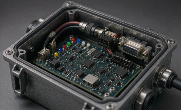
Our baseline BMS thresholds for mobility packs: charge inhibited below 0 °C, resumed at +5 °C, derated to 0.2–0.5 C between 0 and 15 °C; discharge derated from 55 °C and cut at 60–65 °C; cell over-voltage at 3.65 V ±25 mV, under-voltage at 2.50 V; over-current at 1.2× continuous for 10 s and 3× peak for 5–10 s; short-circuit hardware latch in under 200–500 µs.
Containment is then three layers. LFP chemistry is the first and most important. The second is propagation control: 0.5–1.0 mm mica or ceramic paper between cells, an intumescent or ceramic-fibre liner under the lid, and a defined vent path that directs gas away from the seat foam and away from the occupant. The third is an independent alarm.
That third layer is the one people skip, and it should not be skipped. A BMS that has latched off is not an alarm — it is a silent pack. We recommend a standard smoke alarm in whatever room the chair charges in, and for care homes and fleet deployments a temperature or volatile-organic sensor at the charging position. Thermal events cluster during charging and the hour after it, which in this application almost always means overnight, in a bedroom.
The passive rules matter just as much: charge on a non-combustible surface — concrete, tile, or a metal tray — never on carpet, a bed or a sofa. Keep 0.5–1 m from combustibles. Keep the egress route clear.
7. Charging Location, Oxygen-Enriched Atmospheres and Night-Time Risk
Overnight charging is not a bad habit that users should be lectured out of; it is the only thing that works. Range is limited, the chair has to be ready at 8 am, and a charge takes four to eight hours at 0.2 C. So the highest-risk operation in the entire product lifecycle happens unsupervised, in a bedroom, for six to ten hours, five nights a week. The engineering has to accept that and design around it rather than pretend otherwise.
Which brings me to the hazard that is almost never discussed in mobility literature: home oxygen. A significant share of powered wheelchair users also use supplemental oxygen, typically 1–6 L/min by nasal cannula, from a concentrator that runs around the clock. NFPA 99 defines an oxygen-enriched atmosphere as anything above 23.5% oxygen by volume at atmospheric pressure. In an enriched atmosphere, materials that merely smoulder in air burn vigorously, ignition energy falls substantially, and flame spread accelerates — the same molten polymer droplet that goes out on a tile floor becomes an ignition source.
The practical rule we publish: the charging position must be at least 2 m from any oxygen source, in a ventilated room, and the concentrator must not be shut inside a cupboard. Do not charge in the hallway either. A chair parked in a corridor with a charger lead across the floor is a trip hazard for everyone and a blocked egress route for the one person who cannot step over it.
Two smaller items that cause outsized trouble. First, coiled extension leads: a 10 A charger on a coiled 10 m reel can drop enough voltage to make the charger run hot and cycle its output, which stresses it and confuses taper termination. Use a wall outlet, or a correctly rated lead that is fully unwound. Second, multi-user settings. In care homes and rehab wards we specify a dedicated charging room — non-combustible surfaces, roughly 1 m spacing between chairs, a smoke alarm, and a written rule that any pack that is swollen, hot to the touch, smells sweet or sharp, or has a cracked case is taken out of service immediately and quarantined outdoors in a metal cabinet at 30–50% SoC, away from the building. Not in the corridor. Not in the sluice room.
8. Flying with a Powerchair: UN38.3, IATA and the 300 Wh Rule
Air travel is where the regulatory side of lithium battery safety becomes concrete for users, and where a surprising number of packs are simply non-compliant.
Start with the baseline. Every lithium cell and battery must pass UN Manual of Tests and Criteria, Sub-section 38.3 before it is transported at all: T1 altitude simulation, T2 thermal cycling, T3 vibration, T4 shock, T5 external short circuit, T6 impact or crush, T7 overcharge, T8 forced discharge. Ask for the test summary document. A marketing “certificate” with a logo and no test-report number is not evidence.
Under the IATA Dangerous Goods Regulations, lithium-ion batteries powering mobility aids are accepted on the condition that the battery type has passed UN38.3, terminals are protected against short circuit, the battery is securely attached to the chair or the chair is designed to protect it, and the circuit is isolated where the design allows. The widely applied size limit is 300 Wh per battery; up to one spare of up to 300 Wh, or two spares of up to 160 Wh each, may typically be carried subject to the operator’s approval.
The arithmetic catches people out. Watt-hours are nominal voltage times amp-hours, so a 25.6 V, 50 Ah pack is 1,280 Wh. That is over the 300 Wh threshold and it is handled as an approved item under the dangerous-goods process — not as a cabin spare. A smaller 25.6 V, 10 Ah pack at 256 Wh fits under the limit. Both numbers should be printed on the pack label, permanently, not on a removable sticker.
The checklist we hand to users and their travel agents:
- Get the Wh rating in writing on the pack label and on the paperwork.
- Notify the airline at least 48 hours ahead. Ground handling decisions take longer than the one hour most carriers formally ask for.
- Carry the datasheet and the UN38.3 test summary, printed.
- Photograph the removal and re-installation sequence and tape that sheet to the chair. Battery removal at a gate is done under time pressure by people who have never seen your chair.
- Protect the terminals and the connector with the supplied caps.
- Never fly with a damaged, swollen or recalled pack.
And the regulatory picture is moving. The FAA Reauthorization Act of 2024 directed further US rulemaking on the safe transport of lithium-ion batteries used in wheelchairs, and the direction of travel is clearly toward tighter labelling, clearer handling instructions and better training for ground staff. Building a compliant label and a documentation pack into the product now is far cheaper than retrofitting it later.
9. Commissioning, In-Service Inspection and Retirement Criteria
Commissioning Checks That Actually Catch Problems
A pack that leaves the factory correct can be installed incorrectly. These are the six checks we require at handover, and they are the ones that find real faults:
- Visual. No swelling, no cracked case, no corrosion, connector keyed and fully seated.
- Torque. M6 power terminals 8–10 N·m, M8 12–15 N·m, witness-marked.
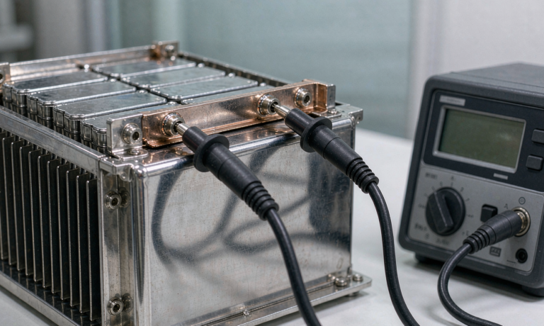
- Insulation resistance. 500 V DC between the pack terminals and the case or chassis. The generic minimum is 100 Ω per volt of nominal, so a 29.2 V pack passes at about 3 kΩ — but we reject anything under 1 MΩ, because a healthy pack measures in the tens of megohms.
- Static cell spread. Reject a new pack showing more than 30 mV between the highest and lowest cell at 40–60% SoC.
- Capacity. A full C/5 discharge, or a controlled on-chair run test, compared against the nameplate.
- Charger verification. Log one complete charge at the pack terminals. Confirm the CV point, confirm the taper termination current, and confirm that no equalisation pulse appears anywhere in the curve. This last one is the check that catches the failure mode in section 3.
In service: a monthly visual and connector check, a quarterly capacity spot-check, and an annual insulation and torque re-check. After any fast charge, run an infrared survey of the pack and its terminals. Investigate any temperature rise above 20 K against the coolest pole; take the chair out of service above 30 K.
When to Retire a Pack
Retire at 80% of nameplate capacity, or when DCIR reaches 1.3× beginning-of-life, or on any of the following regardless of capacity:
- Repeated BMS protection trips with no external cause found.
- Static cell spread above 100–150 mV that balancing cannot close.
- Any physical damage, case swelling, or cracked enclosure.
- Any cell that has been over-discharged below 1.5 V or overcharged above 4.0 V.
- Any pack that has been in a fire, in a vehicle crash, or submerged.
Spare packs store at 30–50% SoC, 10–25 °C, topped up every six months, in a non-combustible cabinet. And a retired pack is not household waste — it goes to a licensed recycler with the transport documentation that applies to lithium batteries, never into a general waste bin where a compactor truck will find it.
FAQ: Lithium Battery Safety for Mobility Devices
Are lithium batteries safe to use in a powered wheelchair?
Yes — and in most cases they are safer than the AGM batteries they replace, provided three conditions hold: the chemistry is lithium iron phosphate, the charger has a genuine LiFePO4 profile with any equalisation stage disabled, and the pack uses a single BMS covering the whole series string. The safety advantage comes from LFP’s thermal margin — self-heating onset around 180–210 °C against roughly 120–150 °C for high-nickel NMC — and from a protection system that will not open the circuit during regenerative braking.
Can I drop a lithium pack into my existing chair without changing the charger?
Almost never. A 24 V lead-acid charger holds float at 27.0–27.6 V, which is 3.38–3.45 V per cell on an 8S LFP string and accelerates calendar ageing, and many apply periodic equalisation pulses at 31–32 V, which is 3.88–4.00 V per cell and will trip the BMS. Cold-weather temperature compensation makes it worse by raising voltage exactly when lithium must not be charged. Budget for a matched charger with the pack.
LFP or NMC — which is safer for a mobility scooter?
LFP, without much debate for this application. You give up roughly 30–40% in volumetric energy density, but you gain about 100 °C of thermal margin, no cathode oxygen release, and two to three times the cycle life. Since a scooter has fixed, known space and a user sitting directly above the pack, the margin is the right trade.
How do I know when a mobility battery is becoming unsafe?
Watch for five precursors: sustained cell temperature rise above 1 °C per minute; more than 10–15 K between the hottest cell and the pack average; resting cell divergence above 50 mV that keeps growing; DCIR above 1.3× beginning-of-life; and voltage sag under a known load more than 20% greater than the IR drop predicts. Any one of those on its own is a reason to stop using the pack and have it tested.
Can I take my wheelchair battery on a plane?
Yes, subject to limits. The battery type must have passed UN38.3, terminals must be protected, and the battery must be secured to the chair or carried as an approved spare. The common threshold is 300 Wh per battery, with typically one spare up to 300 Wh or two spares up to 160 Wh each. A typical 25.6 V, 50 Ah pack is 1,280 Wh and is well over the spare limit, so it travels through the airline’s dangerous-goods process. Notify the carrier at least 48 hours ahead and carry the printed UN38.3 test summary.
How long should a mobility lithium battery last?
LFP packs in daily mobility service typically deliver 3,000–6,000 cycles at 80% depth of discharge, which at 300–500 cycles per year means roughly five to eight years in calendar terms, with capacity dropping to the 80% retirement threshold somewhere in that window. Heat is the main lever: every 10 K rise above about 25 °C roughly doubles the calendar ageing rate, so where the chair is parked and charged matters as much as how it is ridden.
Is it safe to charge overnight?
It is safe if the environment is right, and it is unavoidable in practice. Charge on a non-combustible surface, keep 0.5–1 m clearance from combustibles, keep the egress route clear, use only the matched charger on a wall outlet rather than a coiled extension lead, and — if oxygen is used in the home — keep the charging position at least 2 m from the oxygen source and concentrator. A smoke alarm in the charging room is the cheapest detection layer you can add.
What should I do with a swollen or damaged pack?
Stop using it immediately, do not attempt to charge it, and do not puncture it. Move it outdoors to a non-combustible surface or a metal cabinet, away from the building and away from anything that can burn, ideally at whatever state of charge it holds. Do not put it in a general waste bin or a household recycling bin. Contact the supplier or a licensed lithium battery recycler for collection and disposal.
Building a Safer Mobility Pack
If there is one thing I would like a distributor or a fleet buyer to take from this article, it is that mobility safety is not a single specification line. It is a chain: chemistry choice, charger algorithm, BMS architecture around regenerative braking, mechanical retention under crash loads, thermal containment, charging environment, transport compliance, and a retirement rule that someone actually enforces. Break any link and the rest of the chain does not help.
At Horizon Power we treat mobility as the hardest application we build for, not the easiest — and we measure our lithium battery pack designs against the question that matters here: if this pack fails, can the person sitting on it get out? Everything above is a way of making sure the answer is yes, with minutes to spare.