Lithium Battery Integration for Solar Kits
I am Karl Huang, Senior Lithium Battery Engineer at Horizon Power. I have spent nine years integrating lithium battery packs into products that other people designed, and solar kits are the most instructive category we work on. A solar kit looks like a simple box: a panel, a controller, a battery, a few outlets. In the field it behaves like a tightly coupled system in which the battery gets blamed for almost everything.
That blame is usually misplaced. Across the kits we have supported through root-cause analysis — portable power stations, off-grid lighting kits, solar home systems, mobile field-power trailers — roughly 55 to 65 percent of returns labelled “battery failure” turned out to be integration faults: a charge profile written for lead-acid, an array string that over-volts the controller on a cold morning, a 12 V harness that drops seven percent of the energy in the cable, a connector that ran at 2 milliohms instead of 0.3, or an inverter that tripped on low-voltage disconnect while the pack still held 40 percent state of charge. The cells were fine. The interfaces were not.
The discipline also scales in both directions. The same interface logic that decides whether a 1 kWh portable kit survives its second summer is what governs a 30 kWh home energy storage system, and it is why the pack we build for a weight-critical drone battery application — where every gram of harness and every milliohm of contact resistance is fought over individually — ends up with fewer field faults than a kit four hundred times its size. Integration rigour, not cell quality, is usually the difference.
This article is the integration playbook. It is not a lithium battery design article — we have covered cell selection and pack construction elsewhere. It is about the seam between the pack and everything around it: the charge controller, the array, the inverter, the wiring, the enclosure, the user, and the service technician. Every number here comes from kits we have commissioned, instrumented, and in too many cases torn down after a warranty claim.
Why Integration, Not the Pack, Decides Solar Kit Field Life
When a customer tells me a solar kit battery died in eight months, my first question is never about the cells. It is about the three interfaces that connect the pack to the rest of the kit, because those interfaces determine what the cells actually experience.
The Three Interfaces That Decide Everything
Every solar kit has exactly three electrical interfaces around the battery, and each one can quietly destroy a good pack:
- The charge interface. The charge controller decides voltage, current, and termination. A controller running a lead-acid algorithm on a lithium battery pack will under-charge, over-charge, or hold the pack at 100 percent indefinitely — all three shorten life.
- The discharge interface. The inverter and DC load ports decide current magnitude, surge behaviour, and the low-voltage cutoff point. A cutoff set too high strands usable capacity; set too low, it lets the BMS trip first and teaches users to distrust the gauge.
- The data interface. The BMS either talks to the controller or it does not. Open-loop systems run fixed profiles and guess; closed-loop systems receive real charge-current limits and voltage targets from the pack once per second.
Get all three right and an LFP pack in a solar kit will deliver 3,000 to 6,000 cycles to 80 percent capacity. Get one wrong and you will see 600 to 1,200 cycles with a failure mode that looks electrochemical but is not.
What the Return Data Actually Shows
Our own tear-down statistics on roughly 400 warranty units over three years break down like this:
- Charge-profile mismatch: 24 percent. Mostly float charging and, in cold climates, charging below 0 degrees C without a temperature cutoff.
- Termination and connection heating: 19 percent. Loose crimp lugs, undersized cable, oxidized ring terminals, connectors run above rating.
- Controller over-voltage events: 11 percent. Cold-morning array open-circuit voltage exceeding the MPPT input rating.
- Thermal enclosure issues: 9 percent. Controller and inverter heat soak baked into the pack in a sealed box in full sun.
- Genuine cell or BMS defects: 21 percent. Manufacturing escapes, weld failures, moisture ingress, balancer faults.
- No fault found: 16 percent. Usually a low-voltage disconnect or a user-interface misunderstanding.
Only one return in five was really the cell. That is the business case for doing integration engineering properly, and it is why I insist on reviewing the whole kit rather than the pack datasheet when a customer asks for a custom battery solution.
Start From the Loads and the Sun, Not From the Pack
The most common integration error is sizing backwards: pick a battery, then find an array and a controller that roughly match. Integration works in the other direction. You start with what the kit must power and how much sun the site actually gets.
The Three-Number Load Audit
Before anyone talks about amp-hours, I want three numbers from the customer’s load list:
- Daily energy in watt-hours. Every load’s wattage multiplied by its run hours, summed. This sizes the array and the pack’s usable energy.
- Peak continuous power in watts. The 15-minute average of the worst realistic combination of simultaneous loads. This sizes the inverter and the continuous discharge rating of the pack.
- Surge power and duration. Motor and compressor starting current, typically 3 to 7 times running current for 0.5 to 3 seconds. A 200 W refrigerator with a locked-rotor draw of 1,200 W for one second is a completely different inverter requirement than 200 W of LED lighting.
Teams that skip the surge number buy an inverter that thermally cycles for a year and then fails, and they blame the battery because the symptom is “the power cut out.”
From Loads to Array and Pack
Array sizing is arithmetic, but the efficiency stack is where estimates go wrong. Daily array energy is:
kWh per day equals kWp of array, times peak sun hours for the site and month, times a system efficiency of roughly 0.70 to 0.80. That efficiency factor is not pessimism; it is the product of module temperature derating (crystalline silicon loses about 0.35 to 0.45 percent of power per degree C above 25 degrees C cell temperature, and a roof-mounted module runs 20 to 30 K above ambient), soiling and mismatch (3 to 8 percent), wiring and connection losses (2 to 4 percent), MPPT tracking and conversion losses (2 to 6 percent), and charge and discharge coulombic losses (3 to 6 percent for LFP).
Pack sizing then follows from autonomy. I recommend two to three days of autonomy for critical loads and one to one and a half days for discretionary loads, on top of a depth-of-discharge policy. For a lithium iron phosphate pack I design to 80 to 90 percent DoD routinely; the extra headroom in the nameplate is what lets the BMS balance and what absorbs a cloudy week without a deep-discharge trip.
The Charge-Rate Check Everyone Forgets
Once you know the array size, check the charge C-rate against the pack. A 100 Ah, 12.8 V LFP pack charged by a 400 W array sees about 31 A, or 0.31C — comfortable. The same pack behind a 3 kW array would see about 234 A, or 2.3C, which is four to five times what the cells accept continuously.
The fix is not a smaller array. Overpaneling is good engineering: it harvests meaningful energy in winter and on overcast days, and modern MPPT controllers limit their output current rather than passing everything through. The rules I hold to are:
- Array nameplate power up to 1.2 to 1.5 times the controller’s rated output current is acceptable on quality MPPT units — check the datasheet for an explicit DC output current limit, because only that limit is a guarantee.
- The controller’s configured maximum charge current must be at or below the pack’s continuous charge rating, which for most LFP cells is 0.5C and for high-power cells 1C.
- The BMS must still be the last line of defence. If the controller’s limit is wrong, the BMS over-current protection has to open before the cells see sustained overcharge.
Charge-Control Topology: PWM, MPPT, and All-in-One Power Stations
Topology choice is an integration decision, not a components decision, because it sets the array voltage, the wiring gauge, and the enclosure thermal budget.
Where PWM Still Makes Sense
A PWM controller is essentially a switch that connects the array directly to the battery and disconnects it when the voltage limit is reached. The array is therefore pulled to battery voltage, which means it operates far from its maximum power point. On a 12 V system with a nominal 60-cell module whose Vmp is around 30 V, you throw away roughly half the module’s available power.
PWM still wins in three narrow cases: very small kits under about 100 W where the efficiency loss costs less than the controller’s own quiescent draw; kits where the module’s Vmp is deliberately close to battery voltage (a 36-cell “12 V nominal” module with Vmp around 18 V loses only 10 to 15 percent against PWM); and ultra-low-cost products where a five-dollar board is the entire point. Everywhere else, MPPT pays for itself within one to two seasons.
MPPT: Matching the Array to the Controller
MPPT controllers convert surplus array voltage into charge current, with conversion efficiencies of 94 to 98 percent at mid-load. The measured harvest gain over PWM ranges from 10 percent in hot, steady conditions to 30 percent or more in cold weather and low irradiance — exactly the conditions when a solar kit owner most needs energy.
The integration work is in the voltage match. Three numbers must agree:
- String open-circuit voltage at the record low temperature. Crystalline silicon Voc rises about 0.25 to 0.35 percent per degree C below 25 degrees C. Two 40 V Voc modules in series give 80 V at STC; at minus 20 degrees C that becomes roughly 90 to 92 V.
- Controller maximum input voltage. This is an absolute rating, typically 100 V, 150 V, 250 V, or 450 V for larger units. Exceeding it even briefly destroys the input stage, and it is not a warranty-covered failure.
- Design margin. I require string cold Voc at or below 80 percent of the controller’s maximum input rating. On the example above, 92 V needs a 150 V controller, not a 100 V one.
The same cold-temperature correction also applies to the DC cable and connector voltage ratings, which are routinely specified at STC and then violated in January.
All-in-One Power Stations: Convenience With Three Hidden Constraints
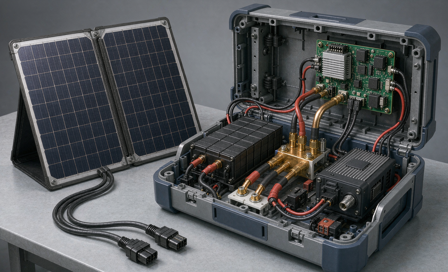
Integrated portable power stations put the MPPT, inverter, DC-DC outputs, and lithium battery pack in one enclosure. They are excellent products, and they constrain integration in three ways worth designing around:
- Shared thermal volume. Controller losses of 2 to 6 percent of throughput plus inverter losses of 5 to 10 percent all end up as heat beside the cells. See the thermal section below — this is the single most under-engineered aspect of these products.
- Fixed charge profile. You inherit the manufacturer’s lithium battery algorithm. Verify it is genuinely CC/CV with tail-current termination and no float, not a lead-acid profile with a lithium label.
- Serviceability. If the pack is potted or glued in, the whole unit becomes the spare part. For fleet customers I specify a field-replaceable pack with a keyed connector and a documented torque spec, even if it costs 8 to 12 percent more in enclosure work.
Voltage Windows and String Counts: Making Three Datasheets Agree
The battery, the controller, and the inverter each publish a voltage window. Integration is the work of making those three windows overlap across the full temperature range, not just at 25 degrees C.
Nominal Voltage Is a Label, Not a Window
Lithium iron phosphate packs are described as 12.8 V, 25.6 V, or 51.2 V, which corresponds to 4, 8, or 16 cells in series at 3.2 V nominal. The real operating window is wider, and every device on the bus must tolerate it:
- End-of-charge: 3.55 to 3.65 V per cell, giving 14.2 to 14.6 V on a 12.8 V pack.
- Rest after charge: about 3.35 to 3.40 V per cell, around 13.4 to 13.6 V.
- End-of-discharge under load: 2.50 to 2.80 V per cell, or 10.0 to 11.2 V on a 12.8 V pack.
A controller or inverter specified only for “12 V lead-acid” usually expects 10.5 to 15.0 V, which is workable, but its low-voltage disconnect behaviour is the problem. Lead-acid sag is a useful state-of-charge signal; LFP sag is nearly flat until it falls off a cliff. An inverter with a fixed LVD at 11.5 V will cut off an LFP pack that still has 25 to 40 percent usable capacity left, because under load the pack sits at 12.5 to 12.8 V for most of the discharge and then drops fast in the last 10 percent.
Why Drop-In Lead-Acid Replacement Needs Re-Engineering
Retrofitting a lithium battery pack into a kit designed for lead-acid is popular and mostly successful, with three mandatory checks:
- Charge voltage. Lead-acid equalization modes run 14.8 to 15.5 V and must be disabled; on LFP that is above the cell’s 3.65 V limit and will trip the BMS or, on a pack with no over-voltage protection, plate lithium.
- Temperature compensation. Lead-acid chargers raise voltage in cold weather by roughly minus 3 to minus 5 mV per degree C per cell. On LFP that pushes charge voltage up exactly when the cells cannot accept current. Compensation must be disabled and replaced with a hard charge inhibit below 0 degrees C.
- Charge current. LFP accepts current far more readily than lead-acid, so an old charger sized for a 0.1C lead-acid charge may be fine, but a modern high-output charger may exceed the pack’s limit. Verify against the pack rating, not the old battery’s.
The Charge Profile Handshake: Absorb and Float Are Lead-Acid Habits
If I could change one thing across the whole solar kit industry, it would be the persistence of float charging. It is correct for lead-acid and wrong for lithium iron phosphate.
What an LFP Profile Should Look Like
A proper lithium battery charge profile has exactly two stages and then stops:
- Constant current at 0.2C to 0.5C for typical solar kits, up to 1C only on cells explicitly rated for it, until the pack reaches the per-cell limit of 3.55 to 3.65 V.
- Constant voltage at that limit until charge current falls to a termination threshold of 0.02C to 0.05C, at which point charging stops entirely.
- No float, no trickle. Holding an LFP pack at 13.5 to 13.8 V indefinitely keeps it at 100 percent state of charge, and calendar ageing at 100 percent SoC and 25 degrees C is roughly twice the rate of ageing at 50 percent SoC. For a kit that sits idle for weeks, I specify a storage mode that discharges to 40 to 60 percent SoC and a maintenance charge that only re-engages below about 30 percent.
Where a full charge is genuinely needed — before a forecast outage, or to give the balancer time to work — I schedule it deliberately: one full charge every one to two weeks, held at the top for two to six hours so passive balancers can correct cell drift, then back to a partial state of charge.
Temperature Rules That Are Non-Negotiable
Lithium plating is the single most damaging reversible-to-permanent failure mode in these kits, and it happens when lithium metal deposits on the anode instead of intercalating. The conditions are well understood:
- Charging below 0 degrees C is prohibited at any meaningful rate. Our BMS blocks it with a sensor on the cell, not on the enclosure.
- Recovery hysteresis: charging resumes at plus 3 to plus 5 degrees C, not at 0. The gap prevents a chattering controller from cycling the pack across the threshold dozens of times on a marginal morning.
- Rate derating: 0.05C to 0.1C between 0 and 5 degrees C, 0.2C to 0.5C between 5 and 15 degrees C, full rate above 15 to 20 degrees C.
- Discharge limit: 55 to 60 degrees C cell temperature, with derating beginning around 50 degrees C.
Discharge in cold weather is safe but weak. At minus 10 degrees C an LFP pack delivers 80 to 85 percent of rated capacity and at minus 20 degrees C about 70 to 75 percent, with DC internal resistance roughly two to four times the 25 degrees C value. That resistance increase is what triggers premature low-voltage cutoffs on cold mornings, not capacity loss. It is also the reason I discuss sodium-ion battery options with customers whose kits live in unheated spaces: a sodium-ion pack retains 85 to 90 percent of capacity at minus 20 degrees C and can accept charge at 0.2C to 0.3C without any heater, which deletes a component, a parasitic load, and a whole failure branch from the integration.
BMS-to-System Communication: Closed Loop or Open Loop
Communication is the interface most often left on the table. A lithium battery pack with a silent BMS forces the rest of the kit to guess, and guesses are what produce the 24 percent charge-profile failure rate in our return data.
What a Closed-Loop System Gives You
In a closed-loop configuration the BMS broadcasts, at 1 to 10 Hz: pack voltage, current, state of charge, state of health, highest and lowest cell voltage, two or more temperature points, and — critically — the currently permitted charge and discharge current limits and the instantaneous target voltage. The controller then tracks a target it did not invent.
The practical benefits are concrete. Cold-start protection becomes real rather than assumed, because the BMS reduces the charge-current limit as cell temperature falls and the controller honours it instead of pushing a fixed 30 A into a frozen pack. Cell imbalance is managed by holding the top voltage until the balancer catches up rather than terminating on a fixed timer. End-of-life degradation is handled gracefully, because a pack at 80 percent SoH announces a lower current limit instead of being charged like a new one.
Protocol and Documentation Requirements I Write Into Specifications
When a customer asks Horizon Power for a custom battery solution for a solar kit, these are the data-interface requirements on the drawing:
- An open, documented protocol. CAN 2.0B at 250 or 500 kbit/s with a published DBC file, or Modbus RTU over RS485 with a published register map. I reject proprietary hexadecimal protocols, because a closed protocol makes the pack unintegratable, unauditable, and un-replaceable — and we have declined procurement on exactly that basis.
- Latched fault registers with timestamps. When a protection event trips six weeks after commissioning, the only way to know whether it was over-current, over-temperature, or cell under-voltage is a latched register that survives power cycles.
- Graceful degradation. On communication loss the controller must fall back to a conservative fixed profile, not to the last received values. Last-value-hold is how a disconnected cable becomes an overcharged pack.
- Broadcast limits treated as hard constraints. A controller that treats the BMS current limit as advisory is not closed-loop; it is open-loop with extra steps.
Wiring, Termination, and the Physics of Low-Voltage DC
Low-voltage DC is unforgiving. At 12.8 V, every milliohm matters, and most solar kit wiring problems I investigate are arithmetic that nobody did.
Voltage Drop: Do the Sum Before Choosing the Cable
Copper resistivity is 1.72 x 10 to the minus 8 ohm-metres at 20 degrees C, rising about 0.4 percent per degree C. The design target I use is 3 percent total drop on the DC power path, 5 percent absolute maximum.
Worked example: a 12.8 V kit drawing 100 A with a 3 m cable run, so 6 m of conductor round trip. With 25 mm squared cable, resistance is about 0.00069 ohm per metre times 6 m, or 4.1 milliohms. At 100 A that is 0.41 V, or 3.2 percent — borderline. With 16 mm squared the same run gives 6.5 milliohms, 0.65 V, and 5.1 percent — too much. At 25.6 V the identical 16 mm squared run drops only 2.5 percent, and at 51.2 V just 1.3 percent.
That is the integration lesson in one calculation: doubling the system voltage cuts resistive losses fourfold at the same current. For any kit above about 1 kW continuous or with cable runs beyond 2 or 3 m, I push the architecture to 48 V nominal and let a DC-DC converter serve the 12 V loads. It is cheaper than the copper you would otherwise buy, and it removes the most common source of “my battery seems weak” complaints.
Terminations Are Planned Consumables
A bolted copper joint should measure 0.2 to 0.5 milliohms. Field data says degraded joints reach 1 to 3 milliohms before anyone notices. The arithmetic is stark: at 100 A, 0.25 milliohms dissipates 2.5 W and stays cool, while 2 milliohms dissipates 40 W and melts its own housing.
Practices that hold up in the field:
- Calibrated torque with a marking pen. M6 terminals at 8 to 10 Nm, M8 at 12 to 16 Nm, M10 at 20 to 25 Nm. Mark every joint, then re-torque after the first 50 operating hours and at every annual service. Loose terminations are the leading cause of melted lugs in our return pile.
- Correct dies for hydraulic crimps. A lug crimped with the wrong die passes a pull test and fails nine months later. Verify the die against the lug and connector manufacturer’s specification, and cut one crimp per batch for cross-section inspection.
- Strain relief, always. Cable must never carry mechanical load to a terminal. Every harness I review gets a service loop and a clamp within 150 to 300 mm of the termination.
- Anti-rotation and keying. Keyed connectors prevent the one reverse-polarity event that destroys a controller in under a second.
Precharge: The Ten-Dollar Part That Saves a Contactor
Every inverter or high-power DC-DC stage has a DC-link capacitance of 5 to 20 millifarads. Closing a contactor into a discharged DC link looks like a short circuit: peak currents of thousands of amps for a few milliseconds, which welds contactors and pits relays. The fix is a precharge path — a 10 to 22 ohm, 20 to 50 W resistor in parallel with a bypass switch. For 10 millifarads at 51.2 V through 20 ohms, peak current is 2.6 A, the time constant is 0.2 s, and the link reaches 90 percent in about 0.5 s and full charge in roughly 1 s. I spec precharge on anything above about 500 W.
Protection Devices Must Be DC Rated
A 100 Ah LFP pack has internal resistance in the low milliohms and can deliver 3,000 to 5,000 A into a bolted fault. An AC-rated breaker asked to interrupt that will not clear it. Requirements: DC-rated fuses or breakers with an interrupting rating appropriate to the available fault current (Class T, NH, or a DC-rated moulded-case breaker, typically 10 kA or more for larger banks), correct polarity orientation where the device is directional, and an over-current device sized to the cable rather than to the load — protection exists to protect the conductor.
Thermal and Enclosure Integration Where the Controller Also Lives
Solar kits concentrate heat sources next to the one component whose life is most temperature-sensitive. This is where good products become mediocre ones.
Counting the Watts Before Choosing the Box
Heat sources in a typical integrated kit: MPPT controller at 2 to 6 percent of throughput, inverter at 5 to 10 percent, DC-DC converters at 4 to 8 percent, and the pack’s own internal resistance at I squared R. A 1 kW kit running at half power for an hour might dissipate 40 to 70 W total.
Now look at the enclosure. Natural convection from a small plastic case gives a heat transfer coefficient around 5 W per square metre per degree. A 0.3 square metre surface dissipating 40 W reaches a steady-state rise of roughly 27 K above ambient. At a 40 degrees C ambient that puts internal air at 67 degrees C — above the derating threshold and close to the cell limit.
Then add sun. Full-spectrum irradiance at 1000 W per square metre, with an absorptivity of 0.3 to 0.6 on a grey or dark enclosure, adds 300 to 600 W per square metre on the exposed face. A 0.3 square metre dark box in direct sun can gain 150 to 200 W on top of everything else. The cheapest fixes are the best ones: mount the enclosure in the shade of the array, keep it off the ground, use a light-coloured or reflective outer surface, and separate the inverter from the pack with a baffle so the cells are not downstream of the hottest component.
Sealing Versus Breathing
Outdoor kits need ingress protection — IP54 for sheltered locations, IP65 or better for exposed ones under IEC 60529 — but a perfectly sealed enclosure in a humid climate will condense water inside whenever the temperature crosses the dew point. The answer is a breathable vent: an ePTFE membrane with typical air permeability above 500 mL per minute per square centimetre at 70 mbar, plus a drainage path at the lowest point, plus conformal coating or potting on the BMS board. I also require the vent to be mounted where it cannot be directly sprayed, and I specify a desiccant pack with a replacement interval for kits in tropical service.
One mechanical note for kits using advanced cells. A lithium ion battery in a prismatic or pouch format is largely indifferent to modest enclosure pressure, but a semi-solid state battery is not: those cells need a maintained stack pressure in the 0.05 to 0.30 MPa band, and the compliance layer that provides it relaxes over time. If your enclosure is carrying stack pressure rather than a dedicated module frame, vibration and thermal cycling will drop that pressure by 30 to 40 percent within a year, and impedance will climb with it. Keep pressure in the module frame and let the enclosure do weather sealing only.
Sensor Placement
Thermal protection is only as good as its worst-placed sensor. My rules: at least one sensor on the cells, bonded to the cell or busbar, not floating in air; one on the hottest semiconductor heatsink; one measuring ambient intake air. The charge and discharge limits must be driven by the cell sensor, because the cell is the thing that degrades and the thing that can plate lithium.
Load Ports, Load Priority, and the Human Interface
The last integration layer is the one users touch. It also explains a large share of the “no fault found” returns.
DC Native Loads Beat Inverting Everything
A small inverter draws 10 to 35 W just being on. Over 24 hours that is 0.24 to 0.84 kWh — on a 1 kWh kit, the inverter’s idle draw can consume 25 to 80 percent of the pack’s usable energy before any load is connected. Integration guidance that follows:
- Serve every load that can take DC from a DC output. Lighting, USB devices, 12 V refrigeration, routers, and most small electronics are all natively DC.
- Use USB-C Power Delivery for portable electronics: 5 to 20 V up to 100 W under PD 3.0, and up to 240 W under EPR. A buck converter doing 12 V to 20 V runs 92 to 96 percent efficient, against 80 to 90 percent for battery to AC to device.
- Put the inverter behind an enable input with a load-detect or a scheduled window. Auto-standby that drops the inverter below 5 to 10 W of load is worth more than 100 Wh of extra cell capacity in a small kit.
Load Priority and the Low-Voltage Disconnect
Loads should shed in a defined order, not all at once. A two-tier scheme works well: at 20 to 25 percent SoC, shed discretionary loads such as convenience outlets; at 10 percent, open the main contactor. Reserve the last margin for controls and communication so the user can still see what happened.
Set the LVD point by testing, not by assuming. Run the kit at its realistic peak current and record the pack’s terminal voltage at the moment the BMS would trip. Set the system LVD about 0.3 to 0.5 V above that on a 12.8 V pack, so the system shuts down gracefully instead of the BMS cutting power abruptly.
State-of-Charge Display: Be Honest About the Error
LFP open-circuit voltage is flat: between roughly 20 and 80 percent SoC the curve changes only 5 to 10 mV per percent SoC, which is why voltage-based fuel gauges on LFP are wrong by 10 to 20 percent. Coulomb counting is accurate in the short term but drifts, and it needs a reset point.
The integration answer is a hybrid estimator with a documented reset policy: count coulombs, reset to 100 percent when the charger terminates on tail current at the top of charge, and reset to a known low point on controlled discharge. Then require one full charge every one to two weeks so the reset actually happens. Anything else and the display becomes the most complained-about part of the product.
Commissioning, Acceptance, and the Field Service Loop
Integration is not finished at first light. It is finished when the kit has run a documented acceptance sequence and the service path is proven.
First Power: The Sequence I Use
- Insulation check before energising. 500 VDC insulation resistance, reject below 1 M ohm. IEC 62619 requires only 100 ohm per volt, but 1 M ohm is the practical field rejection line and it catches damp harnesses and pinched insulation early.
- Polarity and voltage verification at every interface. Array polarity into the controller, pack polarity into the bus, precharge verification with a scope or a logging meter — confirm the DC link ramps over about a second rather than slamming.
- Torque audit with a calibrated wrench. Do not trust the factory marking; verify it.
- Charge profile verification. Log voltage and current through a full charge. Confirm CC then CV, confirm termination on tail current, confirm no float stage, and confirm the low-temperature inhibit actually blocks charging when you chill a sensor with freeze spray.
Acceptance Criteria
Before a kit design goes into production, it must pass:
- Capacity: C/5 discharge delivers at least 100 percent of nameplate at 25 degrees C from a full CV-terminated charge.
- Worst-case thermal: full rated load at 40 degrees C ambient with the enclosure in simulated sun. Cell temperature below 55 degrees C, cell-to-cell spread below 8 K, and no current derating.
- Surge: the largest motor load starts three times cold without the pack or inverter tripping; record the minimum DC bus voltage during the event.
- Voltage drop: measured at the load terminals under peak current, below 3 percent on the DC path.
- Termination temperature: infrared scan after two hours at greater than 50 percent load; any termination more than 20 K above its neighbour gets reworked, and more than 30 K is a stop-work condition.
- Protection verification: over-voltage, under-voltage, over-current, short-circuit, and charge-inhibit-below-zero each demonstrated once on a bench, not just read from a register.
- Endurance soak: seven consecutive days of a realistic daily profile with no faults, and a full charge at least once in that window.
Designing for the Service Technician
The last piece of integration engineering is the person who opens the box in year three. Requirements that pay for themselves:
- Field-replaceable pack with a keyed connector, a documented torque spec, and a replacement procedure that does not require recalibrating the system.
- Diagnostic access without disassembly — a service port or a mobile app that shows cell voltages, temperatures, DCIR trend, and latched faults.
- A firmware update path that a technician can execute in the field, with versioned, rollback-capable images.
- A spare strategy based on measured failure rates, typically 10 to 15 percent of fleet size as baseline stock plus the repair-turnaround months multiplied by the monthly replacement rate.
- Drop-in compatibility across product generations. If the replacement pack changes series count, the controller and inverter setpoints must change too — and that is a re-commissioning, not a swap.
Kits that ship with this discipline have a service cost per unit per year that is a fraction of those that do not, and the difference shows up in the second year, not the first.
Frequently Asked Questions
Can I replace a lead-acid battery with a lithium battery pack in an existing solar kit?
Usually yes, with three mandatory changes. Disable equalization mode, because its 14.8 to 15.5 V exceeds the LFP cell limit of 3.65 V. Disable temperature compensation, which raises charge voltage in cold weather when lithium cells most need to be protected. And verify charge current against the pack’s continuous rating rather than the old battery’s. Confirm the charge profile is CC/CV with tail-current termination and no float stage.
How much array can I connect before it overpowers the battery?
Overpaneling is limited by the controller, not the array. Array nameplate up to 1.2 to 1.5 times the controller’s rated output power is acceptable on quality MPPT units provided the controller has an explicit output current limit and you configure it at or below the pack’s continuous charge rating, typically 0.5C. Separately, the array’s cold-temperature open-circuit voltage must stay at or below 80 percent of the controller’s maximum input rating.
Why does my kit shut down while the gauge still shows plenty of capacity?
Three candidates, in order of likelihood. First, the low-voltage disconnect is set for lead-acid behaviour and trips on voltage that an LFP pack reaches only in its last 10 to 20 percent — measure terminal voltage at the trip point. Second, voltage drop in the harness: at 12.8 V, a 5 percent drop makes the load see a cutoff before the pack is actually empty. Third, state-of-charge drift from coulomb counting without a recent full-charge reset. Log pack terminal voltage, load current, and cable drop together for one full discharge and the answer will be obvious.
Do I need a battery heater for cold climates?
For lithium iron phosphate, you need charge protection rather than heating. Charging below 0 degrees C causes lithium plating, so the BMS must inhibit charging until cells reach plus 3 to plus 5 degrees C. If you need full-rate charging in genuine cold, heating is the answer, but it adds 100 to 300 W of parasitic load. Alternatively, a sodium-ion battery pack retains 85 to 90 percent capacity at minus 20 degrees C and accepts charge at 0.2C to 0.3C without any heater, which is why we recommend it for unheated installations.
Should the BMS talk to the charge controller?
Yes, for anything above a few hundred watts. Closed-loop control lets the BMS broadcast real charge-current limits and voltage targets based on cell temperature and state of health, which is what prevents cold-weather plating and graceful handling of aged packs. Insist on a documented open protocol — CAN with a published DBC file or Modbus RTU with a register map — and require a conservative fallback profile on communication loss.
What size cable should I use between the battery and the inverter?
Size it for voltage drop and for the over-current device, not for the load alone. Target 3 percent drop on the DC path; at 12.8 V and 100 A over a 3 m run that means 25 mm squared or larger. If the required cable becomes impractical, raise the system voltage to 25.6 V or 51.2 V, which cuts resistive loss fourfold or sixteenfold at the same current.
How often should the pack reach a full charge?
Every one to two weeks. Full charges give the passive balancer time to correct cell drift and give the state-of-charge estimator a reset point, which matters because LFP open-circuit voltage is too flat for voltage-based gauging. Between full charges, holding 40 to 60 percent state of charge minimises calendar ageing, and long-term float at 100 percent roughly doubles the ageing rate.
What does the enclosure need for outdoor service?
IP54 for sheltered locations and IP65 for exposed ones under IEC 60529, a breathable ePTFE vent to prevent condensation, drainage at the lowest point, a light-coloured or shaded exterior to reduce solar gain, and a thermal baffle between the inverter and the cells. Verify with a hot-box test at 40 degrees C ambient under simulated sun: cells below 55 degrees C, spread below 8 K, no derating.