
Battery Solution Maintenance for Equipment
Maintenance is where most battery programmes quietly lose their money. I have spent more than a decade designing and field-supporting custom lithium battery packs, and the pattern is always the same: the cells are rarely the reason a piece of industrial equipment stops working. The reason is a contact that has fretted itself to 200 mΩ, a harness that has been flexed past its bend radius ten thousand times, a state-of-charge gauge that has drifted 18% because nobody recalibrated it, or a fleet of spares that sat at 100% charge in a 40 °C container for eight months.
This guide is written for maintenance engineers and equipment managers who run industrial kit on lithium power — handheld terminals, portable test instruments, inspection gauges, mobile printers, gas detectors, rugged tablets, field metrology gear and the thousands of other devices that no longer make sense on disposable primary cells. It covers what to measure, how often to measure it, how to tell a bad cell from a bad connector, and when to stop maintaining a pack and replace it. Everything here comes from work I have done on real fleets, benchmarked against the standards we design to: IEC 62133-2 for cell and pack safety, IEC 62619 / IEC 62620 for industrial secondary lithium cells, UN 38.3 for transport, and IEC 60529 for the ingress ratings that decide whether a pack survives its environment.
The core argument is simple. A battery solution maintenance programme for equipment is not a cost centre; it is the difference between a pack that delivers 2,000 cycles over six years and one that is scrapped after 400 cycles in eighteen months. The maintenance discipline is cheap. The packs are not.
Why equipment batteries fail differently from consumer packs
The failure physics of a battery inside industrial equipment has almost nothing in common with a battery inside a phone. Consumer packs are optimised for energy density and cost, are cycled gently, and are thrown away when the user gets bored. Industrial packs sit inside equipment that is often treated badly and expected to work for a decade.
Three characteristics dominate:
- Duty cycle is intermittent and peaky. A handheld inspection gauge may draw 200 mA for nine minutes and then 6 A for fifteen seconds when a pump or heater fires. That pulse, not the average current, sets the internal heating and the voltage sag that trips the under-voltage lockout.
- Environment is uncontrolled. I have pulled packs out of equipment that had been left on a dashboard in direct sun at 78 °C surface temperature, and packs that had been cycled at −20 °C in a cold store. Both fail, but they fail in completely different ways: heat drives electrolyte decomposition and SEI growth, cold drives lithium plating on charge.
- The mechanical interface is abused. Equipment is dropped, docked and undocked hundreds of times, dragged by its cable, cleaned with solvents, and hosed down. In my failure statistics across service returns, the connector and harness account for roughly 45–55% of all “dead battery” reports; the cells account for less than a third.
That last number is the one that should reshape your maintenance plan. If you only ever measure capacity, you will chase phantom cell failures for years.
The four numbers that define a maintenance interval
A lithium battery pack gives you four diagnostic signals. Everything else is derived from them. Set your inspection intervals around how fast these move in your application.
| Signal | What it tells you | Typical new value | Investigate when | End-of-life reference |
|---|---|---|---|---|
| Discharge capacity (Ah) | Total usable energy remaining; the primary wear metric | 100% of rated | < 90% of rated | 80% of rated (industrial), 70% (traction) |
| DC internal resistance (DCIR) | Power capability, heat generation, connection health | 25–60 mΩ per 18650-class cell | +30% vs baseline | +100% vs baseline |
| Cell voltage spread (ΔV) | Balancing health, weak cell, uneven thermal environment | < 20 mV at rest | > 50 mV at rest, > 150 mV under load | > 200 mV with passive balancing |
| Self-discharge / rest loss | Micro-shorts, moisture ingress, BMS quiescent draw | 1–3% per month at 25 °C | > 5% per month | Rising trend month over month |
Two rules make these numbers comparable over time, and they are the rules most fleets break:
- Always measure at the same state of charge and the same temperature. DCIR on an NMC cell at 20% SOC and 15 °C can be double the value at 80% SOC and 35 °C. I specify ±2 °C and ±5% SOC as the tolerance window in every test procedure I write. Without it your trend line is noise.
- Record a baseline on day one. Absolute thresholds in a datasheet are population statistics. Your pack’s own baseline is a fact. I ask every customer to log DCIR and capacity at acceptance, at 100 cycles, and at every scheduled service thereafter.
Building a maintenance schedule that matches duty cycles
Calendar intervals are easy to administer and almost always wrong. A pack that does three full cycles a day needs a different regime from one that does three a week. Use the equivalent-full-cycle (EFC) count from the battery management system as the primary trigger and the calendar as a backstop.
My default schedule for industrial equipment
- Every shift or every charge (operator level, 30 seconds): visual check of housing, latch, contacts and cable; note any pack that is unusually hot at end of charge (> 50 °C surface) or that finishes charging suspiciously fast.
- Every 50 EFC or monthly (technician level, 5 minutes): read BMS log — cycle count, min/max cell voltage, peak current, max cell temperature, alarm flags (COV, CUV, OTC, OTD, OCC, OCD). Wipe contacts with > 99% isopropyl alcohol on a lint-free swab. Confirm the SOC gauge agrees with a measured open-circuit check after a 30-minute rest.
- Every 200 EFC or quarterly (engineer level, 30 minutes): DCIR measurement per the method below, capacity verification on a sample pack, SOC recalibration, torque check on the mechanical fixings, gasket and strain-relief inspection.
- Every 500 EFC or annually (programme level, half a day): full capacity test on the whole fleet or a statistically meaningful sample (I use √n + 1 for fleets above 50 packs), infrared scan of contacts under load, review of the failure Pareto, and a decision on spares ratio and repack timing.
For equipment that sits in standby for most of its life — emergency lighting test sets, backup instruments, portable defibrillator-style carts — the calendar becomes the primary trigger, because calendar ageing dominates cycle ageing. An NMC pack stored at 100% SOC and 40 °C can lose 20–30% of its capacity in a year with zero cycles on the counter. Store it at 40% SOC and 20 °C and the same pack loses about 2–4%.
Diagnostic workflow: from symptom to cell-level root cause
When a piece of equipment reports a battery problem, resist the urge to swap the pack and move on. Three minutes of diagnosis tells you whether you have a cell problem, a connection problem, or a gauge problem, and those have completely different fixes.
Step 1 — Measure the pack terminals under load, then the cell stack
Put a 4-wire milliohm meter or a known load across the pack output and measure the voltage drop from the cell tab to the equipment-side contact. If the pack terminal reads 15.8 V but the cell stack reads 16.2 V under a 5 A load, you have 80 mΩ sitting between the cells and the outside world — that is roughly 2 W of heat and a guaranteed premature low-voltage cutout. No amount of cell replacement fixes that.
Step 2 — Read the BMS log before you touch anything
Modern industrial packs log min and max cell voltage, peak charge and discharge current, maximum and minimum cell temperature, cycle count, and every protection event with a timestamp. The log will tell you whether the low-voltage shutdown was caused by one cell collapsing (cell problem) or by the whole stack sagging uniformly (connection, temperature, or genuine end of life). A single cell dropping more than 150 mV below its neighbours under load is a cell fault; all cells dropping together is not.
Step 3 — DCIR on the pack and on each cell
The standard method (aligned with IEC 62620 practice) is a 10-second discharge pulse at or near 1C from a known SOC, with DCIR = ΔV / ΔI taken between the first and tenth second. Do it at the same SOC every time. If the pack DCIR has grown 40% but every individual cell is within 10% of its baseline, the resistance is in the interconnects, the welds or the contacts — not in the electrochemistry.
Step 4 — Capacity verification
A full capacity test means charging to the manufacturer’s upper limit at the specified rate, resting 30 minutes, then discharging at a defined constant current to the cut-off voltage while integrating amp-hours. On a 5 Ah pack at 0.2C that is five hours. For most fleets that is too expensive to do on every unit at every service, which is why I use quarterly sampling plus full-fleet annual testing. If a pack measures below 80% of rated capacity, it has reached end of life for most industrial duty — but check the resistance first, because a pack at 85% capacity with 2.5× baseline DCIR is already useless in a high-pulse application even though the amp-hours look acceptable.
Symptom-to-cause table
| Symptom | Most likely cause | Confirming measurement |
|---|---|---|
| Equipment shuts down at 30–40% indicated SOC | SOC gauge drift, or high DCIR causing sag under pulse | Recalibrate gauge; measure DCIR; compare sag at 1C vs 5C |
| Pack charges to full in 20 minutes | Capacity loss, or one cell hitting COV and terminating charge early | Cell ΔV during charge; full discharge test |
| Pack warm at the connector after use | Contact resistance from wear, fretting or contamination | Milliohm drop across mated pair; thermal image under load |
| Intermittent cut-outs when the unit is moved | Harness fatigue, broken strands at the strain relief, cracked solder joint | Flex test with continuity monitor; visual at strain relief |
| Pack dead after a weekend on the shelf | BMS quiescent draw too high, or a micro-short / moisture path | Quiescent current in µA; 7-day rest loss test |
| Charger refuses to start in cold weather | Charge temperature protection (correct behaviour, not a fault) | Cell thermistor reading vs ambient; verify 0 °C charge limit in spec |
Contacts, connectors and harnesses: the maintenance task nobody schedules
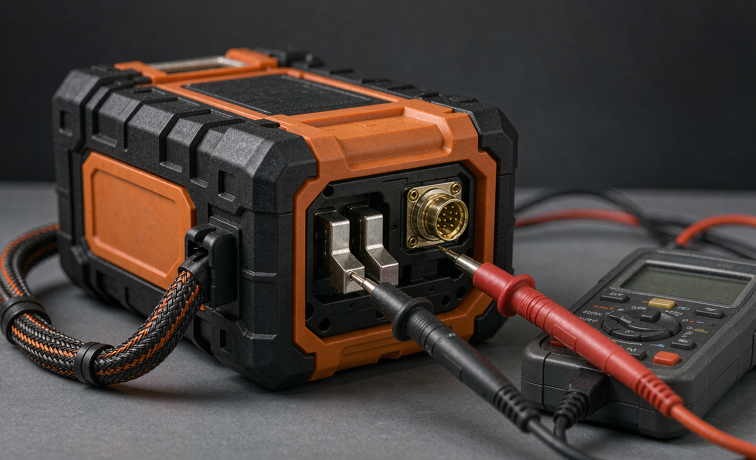
If I could change one thing in every maintenance programme I have reviewed, it would be this: put the connector on the schedule. Blade and spring contacts are mechanical parts with a finite life, and they degrade silently.
What actually happens to a contact
- Fretting. Micrometre-scale motion from vibration or thermal cycling scrubs the plating off the contact surface and oxidises the base metal. Contact resistance climbs from single-digit milliohms to hundreds of milliohms over a few thousand cycles.
- Wear past the plating. Industrial gold flash is typically 0.4–0.8 µm over 2–5 µm of nickel. A contact rated for 5,000 mating cycles is not rated for 5,000 mating cycles of aggressive, misaligned insertion.
- Contamination. Dust, flux residue, hand oils and cleaning solvents all leave films. Some solvents soften the housing and let moisture in.
- Loss of normal force. Spring contacts relax with time and temperature. Once normal force drops, the contact becomes a heater.
The maintenance I specify
- Clean contacts every monthly service with > 99% isopropyl alcohol on a lint-free swab; never use an abrasive, and never use a conductive brush on a live pack.
- Inspect plating for base-metal exposure under a loupe; retire the contact pair when you see nickel or copper showing through on the working surface.
- Verify mated contact resistance is below 5 mΩ for power blades and below 30 mΩ for signal pins, using a 4-wire milliohm meter.
- Check harness strain reliefs and bend radius; replace any harness with visible jacket cracking, and pull-test suspect crimps (a 0.5 mm² crimp should hold well above 80 N per common IPC/WHMA-A-620 acceptance criteria).
- Re-torque mechanical fixings to the drawing value — for the M3 and M4 hardware common in these packs that is typically 0.5–0.6 N·m and 1.2–1.5 N·m respectively, but always follow the pack drawing first.
- Re-seat or replace gaskets on IP-rated enclosures. A hardened silicone gasket turns an IP65 pack into an IP44 pack, and moisture ingress produces exactly the kind of rising self-discharge and erratic cell readings that get misdiagnosed as cell failure.
On cost: a contact set or a harness is a few dollars and ten minutes. A pack is hundreds of dollars and, on custom equipment, months of lead time.
Firmware, BMS logs and SOC recalibration
Almost every industrial lithium battery pack estimates state of charge by coulomb counting, with an open-circuit-voltage correction applied when the pack rests. Coulomb counting drifts. A current-sense error of 1% plus an uncorrected quiescent draw can push the gauge 3–5% per month away from reality, and after six months your operators are reacting to a number that has nothing to do with the pack.
Recalibration is straightforward and belongs on the quarterly task list:
- Charge to the manufacturer’s full-charge termination at the specified rate and temperature.
- Rest at least two hours (open-circuit voltage needs to relax; the relaxation tail on LFP in particular is slow).
- Discharge at a constant, logged rate to the cut-off voltage.
- Integrate amp-hours and write the measured capacity back into the gauge or the BMS configuration.
While you are connected, pull the full BMS log and keep it. Three data fields earn their keep in a fleet database: cumulative equivalent full cycles, maximum cell temperature reached, and the count of protection events. Those three predict failures better than capacity does. I also recommend firmware version control as a formal maintenance record — a pack that was flashed with a different balancing threshold behaves differently from its siblings, and the difference will show up in your trend data as an unexplained outlier.
Storage, transport and spares management
Fleets fail in the storeroom as often as they fail in the field. The rules are not complicated, but they are specific:
- Store at 30–50% SOC. Not 100%, not 0%. At 100% SOC and elevated temperature you accelerate calendar ageing; at 0% you risk the BMS quiescent draw pulling cells below their minimum and permanently damaging them.
- Store at 10–25 °C. As a rule of thumb in the 25–45 °C band, ageing rates increase roughly 1.5–2× for every 10 °C rise. A storeroom that hits 40 °C every summer is a capacity-destroying facility.
- Check stored packs every six months and top up to 30–50% if they have drifted below 25%.
- Rotate FIFO and log storage date on the pack. A pack that has sat for three years has aged even if its cycle counter reads zero.
- For air transport of standalone batteries (UN3480), ship at no more than 30% state of charge, with valid UN 38.3 test summary (T1–T8), correct packaging and labelling per the current IATA Dangerous Goods Regulations and packing instruction PI 965. Batteries installed in or packed with equipment follow PI 966 and PI 967 respectively, and the state-of-charge limit applies to the standalone case.
- Never store a damaged or swollen pack indoors. Move it to a non-combustible, ventilated area or a fire-rated container, and follow your local waste regulator’s guidance for lithium battery disposal.
On spares ratio: for critical equipment I size the spare pool at 10–15% of the installed fleet, not 5%. That number comes from the arithmetic of lead time — if a custom battery solution has a ten-week lead time and your failure rate is 8% per year, a 5% pool leaves you short in the second year every time.
End-of-life criteria and the repack-versus-replace decision
“End of life” means the pack no longer meets the requirement it was specified to meet. Define that threshold before you need it, and write it into the maintenance procedure.
- Capacity < 80% of rated at the specified discharge rate and temperature — the usual industrial threshold.
- DCIR > 200% of baseline, or any value that causes the equipment to trip its low-voltage lockout under normal peak load.
- Cell ΔV > 200 mV at rest after a full charge with the balancer having had time to work.
- Rising self-discharge trend (> 5% per month and climbing) — treat this as a safety signal, not a performance signal.
- Any physical damage: swelling, cracked housing, melted connector, electrolyte smell, or a pack that has been in a fire, immersed, or crushed. These packs are retired immediately regardless of electrical performance.
When a pack reaches end of life, the choice is repack or replace. I use this logic:
- Repack when the housing, connector, harness and BMS are serviceable, the cells are a current production part, and the labour plus cell cost is below roughly 55–60% of a new pack. Repacking keeps the mechanical interface and the equipment certification intact, which on regulated equipment is often worth more than the cost saving.
- Replace when the BMS is obsolete, the failure was caused by an environmental or mechanical problem you cannot design out, or the cell format has changed. Do not repack into a pack whose failure mode you have not diagnosed — you will buy the same failure again in eighteen months.
- Second life is a real option for packs retired at 80% capacity from high-pulse duty: move them into low-rate standby service where the remaining 80% capacity and the higher resistance do not matter. Label them clearly, re-baseline them, and keep them out of the critical fleet.
What I specify in a custom battery solution to make it maintainable
Maintainability is a design decision, and it is made long before the first service interval. When my team at Horizon Power specifies a custom battery solution for industrial equipment, these are the requirements I put on the drawing because I know someone will have to service the pack in year five:
- Accessible diagnostics. SMBus or I2C brought out to the connector, with a documented register map. If the state of health can only be read with a proprietary dongle, nobody will read it.
- Serviceable connectors, not potted ones. Contacts replaceable without destroying the housing; nickel-plated copper power blades with gold-flashed signal pins.
- Cell-level tap access so a technician can measure individual cell voltages without cutting the pack open.
- Mechanical robustness matched to the equipment: strain reliefs with a defined bend radius, fixings with published torque values, and a housing rated to the real ingress requirement (IEC 60529 IP54 for indoor industrial, IP65 or better for washdown and outdoor).
- Thermistors on the hottest cell, not the average cell. A temperature sensor in the wrong place produces a log that says everything was fine.
- A published maintenance procedure with the four baseline numbers, the measurement conditions, and the end-of-life thresholds filled in for that specific pack.
- Certification evidence on file: IEC 62133-2 for the cell and pack, IEC 62619 where the application is industrial stationary or motive, UN 38.3 test summary for transport, and the full test report set for the equipment’s own compliance file.
Every one of those items costs a small amount at design time and saves multiples of it across a fleet’s life.
The maintenance mindset that actually works
The fleets that get six to eight years out of their lithium battery packs are not the ones with the best cells. They are the ones where a technician spends five minutes with a multimeter and a log reader every month, where the connector is a scheduled consumable, where spares are rotated, and where the state-of-health trend is reviewed before something fails rather than after.
Start with baselines. Pick your four numbers, log them under consistent conditions, and let the trend tell you when to act. Budget for contacts and harnesses as consumables. Recalibrate the gauge. Store your spares properly. And when a pack does fail, spend the three minutes to find out whether you lost a cell or a connection — because the answer determines whether your next purchase is a pack or a contact set.
FAQ
How often should lithium battery packs in industrial equipment be tested?
Use equivalent full cycles as the trigger with a calendar backstop: a visual and log check every 50 EFC or monthly, DCIR and SOC recalibration every 200 EFC or quarterly, and a full capacity test every 500 EFC or annually. Equipment that mostly sits in standby should be driven by the calendar instead, because calendar ageing dominates when cycle counts are low.
What state of charge should I store spare battery packs at?
30–50% SOC at 10–25 °C, checked and topped up every six months. Storing at 100% accelerates calendar ageing, and storing near empty risks the BMS quiescent current pulling cells below their minimum voltage, which permanently damages them.
My equipment shuts down at 40% indicated charge. Is the pack dead?
Usually not — that symptom most often means state-of-charge gauge drift or high DC internal resistance causing voltage sag under a current pulse, not lost capacity. Recalibrate the gauge with a full charge, two-hour rest and logged discharge, then measure DCIR. Replace the pack only if capacity is below 80% of rated or DCIR has roughly doubled from its baseline.
Can I replace just the cells instead of buying a whole new pack?
Yes, when the housing, connector, harness and BMS are serviceable and the cells are a current production part; repacking is usually worth it when parts plus labour run below about 55–60% of a new pack. Replace instead if the BMS is obsolete, the cell format has changed, or you have not yet diagnosed the original failure mode.
Which standards apply to maintaining lithium battery packs in industrial equipment?
IEC 62133-2 governs cell and pack safety, IEC 62619 and IEC 62620 cover industrial secondary lithium cells and their performance and reliability testing, IEC 60529 defines the ingress protection ratings that determine whether the enclosure still protects the pack, and UN 38.3 (tests T1–T8) governs transport. Air shipment of standalone lithium-ion batteries under UN3480 additionally requires no more than 30% state of charge under the IATA Dangerous Goods Regulations.
What is the single most common cause of “dead battery” reports in equipment?
The connector and harness, not the cells. In the service-return data I have reviewed, contact wear, fretting, contamination, broken crimps and cracked strain reliefs account for roughly half of all reported battery failures. Cleaning contacts, verifying mated resistance below 5 mΩ on power blades, and replacing harnesses as consumables prevents most of them.
How do I know when to retire a swollen or damaged pack?
Immediately, and regardless of electrical performance. Swelling, a cracked housing, a melted connector, electrolyte odour, or any pack that has been crushed, immersed or exposed to fire goes out of service at once. Move it to a non-combustible, ventilated area or a fire-rated container and follow your local regulations for lithium battery disposal.





