
Battery Solution Reliability for Sensors: How I Specify
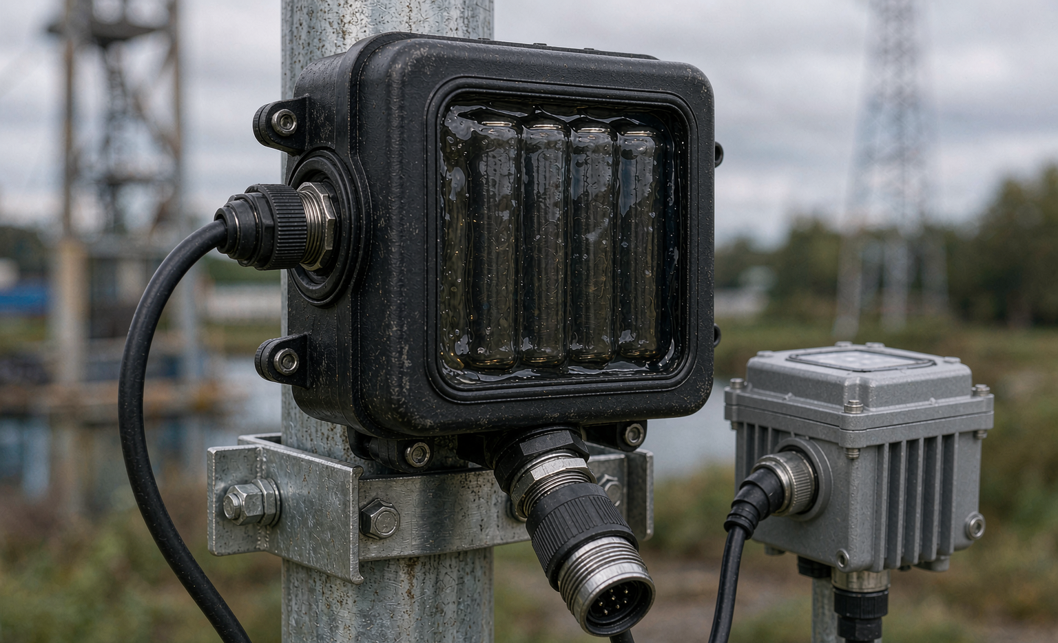
Seven years ago I stood on a ridge in Inner Mongolia looking at a weather station that had gone dark for the third time in eighteen months. The anemometer was fine. The LoRa radio was fine. The firmware was fine. What had failed was the power: a nominally adequate battery pack that had been specified on capacity alone, dropped into an enclosure with no thought for pulse current, sealing, or low-temperature behaviour. The truck roll to replace four D-cells cost more than the entire sensor node.
That job changed how I write a specification. In remote sensing, the power source is not an accessory — it is the component that decides whether your data exists at all. This article is my field guide to battery solution reliability for sensors: what actually kills remote sensor power, how to quantify it before you ship, and how to build a custom battery solution that survives a decade outdoors instead of a season.
Why Sensor Power Fails Before the Sensor Does
Every remote monitoring deployment I have audited fails in one of five ways, and only one of them is “the battery was too small”:
- Pulse current starvation. The node sleeps at 8 µA, then demands a 1.5–2 A burst for 400 ms when the NB-IoT or LTE modem transmits. A cell chosen on amp-hours alone sags below the modem’s 3.0 V cutoff and the module brown-outs — then resets, then transmits again, draining the pack in weeks.
- Thermal mismatch. A primary lithium cell rated at 20 °C may deliver less than half its capacity at −30 °C, while a rechargeable pack simply refuses to charge below 0 °C.
- Ingress. Condensation plus a non-potted PCB equals creeping corrosion across the cell tabs. IP67 on the enclosure datasheet means nothing if the cable gland is torqued to 0.3 N·m.
- Self-discharge and passivation. Over a ten-year design life, a cell losing 1% per year silently consumes 10% of your budget before the load ever sees it; lithium thionyl chloride adds a passivation layer that raises internal resistance during long idle periods.
- Sizing by average instead of worst case. The worst month — shortest solar insolation, coldest nights, highest transmit retry count — is the month that sets your pack size.
Notice that four of those five are reliability problems, not capacity problems. That is the distinction that separates a sensor battery that lasts ten years from one that lasts eighteen months.
Putting Numbers on Reliability
“Reliable” is not a specification. When I review a design I ask for four numbers:
- Annual failure rate (AFR) at the 95% confidence level, derived from field returns or from accelerated testing. For a well-built primary lithium pack in a benign climate, better than 0.3%/year is achievable. Anything above 2%/year will dominate your maintenance budget.
- Capacity retention at end of life. For a ten-year deployment I specify ≥80% of initial capacity at 20 °C after ten years, and ≥60% at the minimum site temperature.
- Internal resistance growth. DCIR doubling from its beginning-of-life baseline is my standard replacement trigger, because it is the leading indicator of pulse-capability loss.
- Operating and storage temperature window. Written as two separate lines: discharge window and charge window. For a lithium battery they are not the same, and conflating them is the single most common error I see in customer specifications.
Once those four numbers are on paper, the chemistry and architecture decisions stop being guesses.
Choosing the Chemistry: Primary vs Rechargeable
For most fixed sensor installations my default is a primary (non-rechargeable) lithium cell, because it removes the single least reliable link in the chain — the charging path. Three chemistries cover 90% of applications:
Lithium Thionyl Chloride (Li-SOCl₂)
The workhorse of metering and remote monitoring: 3.6 V nominal, energy density around 500–700 Wh/L, an exceptionally flat discharge curve, and self-discharge below 1% per year at 20 °C. The −40 °C to +85 °C operating window covers almost every terrestrial site. The catch is passivation: a thin lithium chloride film builds on the anode during storage, raising internal resistance and causing a voltage “dip” on the first high-current pulse. I mitigate it with a hybrid pulse capacitor (an HLC or SPC architecture) that supplies the transmit burst while the cell recovers, and by specifying bobbin-type construction for low-rate service rather than spirally wound cells.
Lithium Manganese Dioxide (Li-MnO₂)
3.0 V nominal, lower energy density than Li-SOCl₂ but far better pulse behaviour and no meaningful passivation. When a customer tells me the node transmits every 60 seconds rather than once an hour, this is usually where I land. It is also the friendlier chemistry for air freight and for consumer-adjacent products.
Rechargeable LFP with Energy Harvesting
When the site has usable solar or wind, a rechargeable lithium battery — normally LiFePO₄ for its 3.2 V nominal, ~4000-cycle life and thermal stability — paired with a small PV panel and a proper MPPT or shunt regulator is the lowest total cost of ownership. Here the reliability question moves to the charge controller: temperature-compensated charge voltage, a low-temperature charge inhibit at 0 °C, and a load-disconnect at a defined state of charge so you never deep-discharge the pack into the knee.
Our team builds all three, and the honest answer is that chemistry selection is a custom battery solution decision — it is driven by duty cycle, site temperature and service interval, not by catalogue habits.
Mechanics, Sealing and the Quiet Killers
Experience has taught me that mechanical detail decides field life more often than cell selection does.
- Potting. For any deployment above IP66 I specify full polyurethane or silicone potting of the cell assembly. It stops vibration-induced tab fatigue, blocks condensation, and makes the pack genuinely tamper-resistant.
- Connectors and glands. Specify the gland torque in the assembly drawing (typically 1.5–2.5 N·m for M12 nylon, more for brass), and use a connector with a rated mating cycle count and a gold-plated contact if the signal is millivolt-level.
- Vent management. Primary lithium cells must never be hermetically sealed with no pressure relief. A sealed aluminium case with a burst rating above 200 kPa is standard practice, and it is also what the transport regulations expect.
- Cable strain relief. Wind loading on a cable that enters a gland without proper strain relief is how water finds its way in. A drip loop in the installation drawing costs nothing.
I verify all of this against IEC 60529 for ingress ratings, IEC 60068-2-27 for shock, IEC 60068-2-64 for random vibration, and IEC 60068-2-52 salt mist for coastal sites. If a supplier cannot show me test reports to those standards, I treat their IP rating as marketing.
Building the Energy Budget
The energy budget is a one-page spreadsheet, and it should be reviewed before the PCB is routed. My template has four columns:
- Sleep current × time. Measure it with a source-measure unit at the pack terminals, not from the MCU datasheet. Real boards leak through pull-ups and unpowered peripherals.
- Transmit pulse: amplitude, duration, count per day. Multiply by 1.5 for retry margin on a marginal RF link.
- Quiescent drain of the pack itself — protection circuit, fuel gauge, self-discharge at the maximum site temperature. Self-discharge roughly doubles for every 10 °C rise.
- Design margin. I will not sign off below 30% margin on a 10-year primary design. On rechargeable systems with harvesting I want 5–7 days of autonomy at the worst-month insolation.
One practical warning: temperature derating is not linear and not symmetrical. A cell that delivers 100% at 20 °C might give 92% at 0 °C, 70% at −20 °C and 45% at −40 °C. Size for the coldest week of the year, not the annual mean.
Qualification Testing I Require Before Release
For every custom battery solution we ship into sensor service, the qualification plan includes:
- UN38.3 transport testing (T1–T8) with an issued test summary — mandatory for any lithium cell moved by air, sea or road, and the first document a freight forwarder will ask for.
- IEC 60086-4 for primary lithium cells, or IEC 62133-2 for rechargeable packs, covering short circuit, abnormal charging, forced discharge and thermal abuse.
- UL 1642 (cell) and UL 2054 (pack) where the end customer requires North American certification.
- Accelerated aging: 90 days at 60 °C on a partially discharged cell is a standard screen; combined with Arrhenius modelling it gives a defensible lifetime projection rather than a hopeful one.
- Thermal cycling: −40 °C to +85 °C, 100 cycles, with DCIR and capacity measured at intervals. This is where poor weld joints and mismatched potting compounds reveal themselves.
- Pulse verification at temperature: apply the real transmit profile at the coldest rated temperature and log the minimum terminal voltage. If it dips within 100 mV of the modem cutoff, the design is not finished.
Monitoring So You Replace Before You Lose Data
Reliability in the field is as much about knowing when a pack is dying as it is about building it well. Three signals matter:
- Loaded voltage sag. Log the minimum terminal voltage during each transmit burst. A sag growing from 120 mV to 350 mV tells me the pack has perhaps six months left.
- DCIR trend. On rechargeable packs we calculate it from the voltage step under a known current pulse. A 25–30% rise over baseline triggers a work order.
- Cumulative charge throughput and temperature-hours. Thermal exposure is the dominant aging driver; logging it lets you rank sites rather than replacing on a fixed calendar.
Design the node so it reports these as two bytes per day. That reporting overhead is trivial compared with one unnecessary site visit.
Specification Checklist
When a customer sends me a request for a sensor battery pack, these are the fields I need filled in before I can quote meaningfully:
- Load profile: sleep current, pulse amplitude and duration, pulses per day, cutoff voltage.
- Design life in years and required capacity retention at end of life.
- Temperature envelope: separate minimum/maximum for discharge, charge and storage.
- Ingress rating, mounting method, cable length and connector type.
- Transport mode and destination (drives UN38.3 and IATA documentation).
- Certifications required by the end market — IEC 62133, UL 2054, or a specific utility standard.
- Annual volume and whether the pack is field-replaceable.
Frequently Asked Questions
How long can a primary lithium battery solution really power a sensor?
With a bobbin-type Li-SOCl₂ cell, a well-managed sleep current in single-digit microamps and one short transmit per hour, ten to fifteen years is a realistic engineering target and not a marketing claim. The limiting factor is usually self-discharge at the site’s maximum temperature, not the amp-hours consumed by the load.
Why does my sensor reset every time the modem transmits?
Almost always pulse current and passivation. The cell’s internal resistance has risen, so a 2 A burst drags the terminal voltage below the module’s cutoff. Fit a hybrid layer capacitor sized for the burst, or move to a chemistry with lower internal resistance such as Li-MnO₂. Measure the terminal voltage with an oscilloscope during transmission — that trace will tell you which of the two it is.
Can I use the same pack for Arctic winter and desert summer?
Not without compromise. A pack optimised for −40 °C discharge usually sacrifices high-temperature storage life, and vice versa. If you genuinely need both, budget for a two-variant product line or an insulated enclosure with a phase-change material, and qualify each variant separately.
Do I need UN38.3 if the batteries are installed in the equipment?
Yes. Cells and batteries contained in equipment still require UN38.3 testing and a test summary; only the packaging and documentation requirements differ. IATA and IMDG both expect the summary to be available on request, and we supply one with every shipment.
Should I choose a rechargeable battery with solar instead of a primary cell?
If the site sees at least two hours of effective sun per day averaged across the worst month, and you can mount a panel that will not be shaded or vandalised, harvesting plus an LFP pack usually wins on ten-year total cost. If the site is shaded, buried, indoors or otherwise energy-poor, a primary pack is more reliable because it removes the charger and the panel from the failure chain.
What is the most common mistake in sensor power design?
Sizing on average current. The load that matters is the worst-case week: coldest temperatures, highest transmit retry rate, and an aging cell with 30% less capacity than when it was new. Design to that week and the other 519 weeks take care of themselves.
Can you build a custom pack for an existing sensor enclosure?
Yes — most of our sensor work is a custom battery solution that drops into an existing mechanical envelope. Send the enclosure drawing, the connector pinout and the measured load profile, and we will return a cell selection, a potting and sealing approach, and a qualification plan with real test data behind it.





