
Battery Solution Design for Equipment: An Engineer’s
If a customer calls me with a stack of drawings and says “design a battery for this machine”, the first thing I do is put the drawings down and ask three questions. What does the machine do, where does it live, and what does the operator expect from the pack on a bad day? Every battery solution design I have shipped for industrial equipment in the last eight years has lived or died by the answers to those three questions. Cells, busbars, BMS chips, enclosures and connectors are all downstream of them. This guide is the design workflow I run on my bench for forklift conversions, AGV fleets, floor scrubbers, agricultural robotics, medical carts and the long tail of “specialty equipment” that never quite fits a catalog pack. The goal is a battery solution that survives three years of shift work without an unplanned service call and that an OEM integration engineer can drop into a CAD assembly without rework.
1. Start With the Load, Not the Cells
The single biggest mistake I see in a custom battery solution is starting with a favorite cell, then bending the rest of the pack to fit it. That approach gives you a pack that looks great on a data sheet and burns through its cycle life in eighteen months on a real factory floor. The honest workflow starts with the load.
I ask the customer for a one-page load profile that includes average current, peak current with duration, regenerative current if any, minimum and maximum ambient temperature, ventilation around the machine, shift length, and the expected calendar life in years. A 24 V floor scrubber that pulls 80 A average and 220 A for ten seconds every minute is a fundamentally different problem from a 48 V AGV that pulls 35 A average and accepts a 2 kW regenerative pulse every time it stops at a station. Both problems can be solved with the same LFP cell family, but the pack sizing, the BMS current sense resistor, and the cooling strategy will be completely different.
If the customer cannot give me that profile, I run a one-week measurement campaign with a current clamp logger on a representative machine. Two hundred dollars of data saves twenty thousand dollars of redesign later, and it lets me defend every number on the spec sheet with a real measurement instead of a guess.
2. Translate Requirements Into Pack Specifications
Once I have the load profile I write down seven non-negotiable specifications before I open a cell catalog. They are the same seven for every battery solution design engagement, regardless of the equipment class.
- Nominal voltage and acceptable voltage window at the equipment terminals.
- Usable energy at the equipment terminals after cable and fuse losses.
- Continuous discharge current, peak discharge current with duration, and peak charge current.
- Operating temperature range at the cell surface, not at the air intake.
- Mechanical envelope including mounting pattern, mass budget, and center of gravity limits.
- Ingress protection, vibration, and shock targets from the equipment specification.
- Certifications required for the destination market, typically UN38.3 plus IEC 62133-2, with regional additions like UL 1973, CE-EMC, or KC.
These seven lines become the contract between me and the customer. If a requirement is unclear I write “TBD” and discuss it before I quote, because vague inputs always become vague packs, and vague packs always come back for warranty.
3. Cell Selection: Why the Cheapest Cells Lose the Job
For most industrial equipment I default to prismatic LFP cells in the 100–280 Ah class. The chemistry is forgiving, the calendar life at 25–35 °C is excellent, and the cost per kilowatt-hour is competitive with NMC once you factor in safety hardware and freight. NMC prismatic cells earn their place only when the equipment demands more than 200 Wh/kg at the pack level or when the volume envelope rules out LFP’s lower volumetric energy density.
Inside the LFP family I refuse cells that come without a factory cycle test report, an X-ray image of the welded stack, and a DCIR curve at three states of charge. The factory report is a baseline. The X-ray catches cold welds. The DCIR curve lets me predict voltage sag at the equipment terminals under the worst case load I measured in step one. A cell that drops 250 mV at 1 C at 50 % state of charge will not survive a 220 A peak in a 24 V scrubber, no matter what the marketing brochure says.
I also reject cells whose date code is more than nine months old at the time of assembly. Calendar aging of LFP is gentle but it is not zero, and I do not want to inherit the previous distributor’s warehouse time.
4. Mechanical Architecture and Busbar Choices
Once the cell is fixed I lay out the pack on paper before I touch metal. A clean mechanical architecture in a battery solution design is the difference between a pack that an OEM integrator can install in twenty minutes and one that takes half a day and three phone calls.
For a 48 V pack I almost always go 16S1P or 16S2P with prismatic cells, because the parallel string count keeps cell-level fusing simple and the series count keeps the BMS part count low. For 24 V packs I prefer 8S1P or 8S2P for the same reason. Higher cell counts are accepted only when the equipment truly needs them, because every additional series string adds balance circuit cost and failure modes.
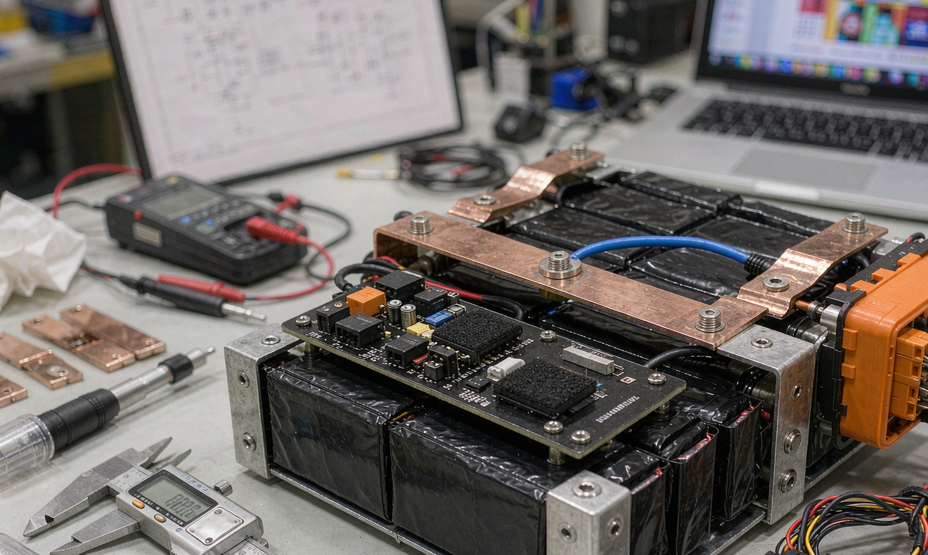
Busbars are laser-welded 0.8 mm nickel-plated copper for packs under 100 A continuous, and bolted tinned copper bars for anything above 100 A. I torque every bolted joint to a written specification, typically 8–12 N·m depending on the stud size, and I mark each joint with a paint pen after torque so a service tech can see at a glance if a bolt has moved. A loose busbar in a vibration-loaded piece of equipment is the most expensive service call in industrial battery work, and a five-second visual inspection is the cheapest fix.
The enclosure is aluminum extrusion or laser-cut sheet steel, depending on cost and IP target. For IP65 I prefer aluminum because the heat path is better and the welding is more forgiving. For IP20 indoor packs I use sheet steel and save 15 % on cost.
5. BMS, Fuses and Functional Safety
A BMS for an industrial battery solution is not a smartphone fuel gauge. It is a functional safety component, and it has to behave correctly when the equipment operator is in a hurry, the ambient is 45 °C, and the contactor has been bouncing for ten thousand hours. I spec automotive-grade BMS ICs from the established vendors, and I require a redundant hardware overvoltage and overcurrent path that does not depend on the same microcontroller that runs the state-of-charge algorithm.
The main contactor is a DC-rated EV-grade part, sized for at least 1.5 times the continuous discharge current of the pack. Pre-charge is mandatory on any system over 200 V pack voltage, and is good practice above 48 V to prevent the inrush that welds inverter bus capacitors. I fuse every parallel string individually with a high rupture capacity DC fuse sized for the worst case short of that string. The fuses do not need to clear fast for an external short, the contactor does, but they do need to clear fast for an internal cell-tab short, and that is a very different fault current.
The CAN or RS-485 communication stack is documented in a register map that the customer can read. Black-box BMS parts that refuse to publish a register map get rejected at the quote stage, because a battery solution that hides its telemetry is a battery solution that fails in the field without explanation.
6. Thermal Design That Survives the Field
Industrial equipment packs live in two thermal worlds. Indoors, a pack bolted to a steel chassis in a 35 °C factory can easily see 50 °C cell surface temperature under continuous load. Outdoors, a pack on a solar-charged agricultural robot in summer can see 60 °C at the surface even before the equipment is turned on. Both extremes shorten cycle life if the design ignores them.
For LFP packs up to about 5 kWh I usually specify passive cooling with a finned aluminum base plate bonded to the cells with a 1.5 mm thermal gap pad of 3 W/mK conductivity. Above 5 kWh, or in any pack with a sustained 1 C charge rate, I move to forced air cooling with a PWM-controlled brushless fan on the negative pressure side. Liquid cooling is reserved for packs above 15 kWh or for equipment that lives at a sustained 2 C discharge rate. The energy cost of the pump and the leak risk make liquid cooling a poor choice below those thresholds.
I always spec the cells to stay below 45 °C under continuous operation and below 55 °C under peak. Above 55 °C the calendar life of LFP starts to halve for every 10 °C, and the customer will notice the capacity loss within the warranty window.
7. Validation and Certification Path
A battery solution design is not finished when the prototype works on my bench. It is finished when it has cleared the certifications the destination market requires and when the customer has signed off on a 90 day production trial in real equipment.
For most of my industrial customers the minimum certification set is UN38.3 for transport, IEC 62133-2 for cell safety, and IEC 62660-2 plus IEC 62660-3 for the pack level cycle and calendar abuse tests. North American customers add UL 1973 for stationary and mobile equipment, and UL 9540A for any pack destined for an energy storage system. Medical carts add IEC 60601-1 collateral. European customers add CE-EMC and the RED if the pack has wireless telemetry.
I run a six-week validation cycle on every new battery solution before I sign the design freeze. Week one is bench characterization at 25 °C. Week two is thermal characterization at −10 °C, 25 °C and 50 °C. Week three is mechanical shock and vibration per the equipment specification. Week four is full cycle life at the worst case duty cycle. Week five is abuse testing including overcharge, overdischarge, external short, drop, and thermal abuse on a sacrificial pack. Week six is paperwork, certification submission prep and a customer factory acceptance test.
That cadence looks slow until you compare it with the cost of a recall. A four week rush job that ships without thermal characterization is the pack that returns in eighteen months with a 20 % capacity loss and a warranty claim. The discipline of the six week validation cycle pays for itself in the second year.
8. FAQ
How long does a custom battery solution design take from kickoff to first production unit?
For a typical 24 V or 48 V industrial pack with off-the-shelf cells, the realistic timeline is ten to fourteen weeks. Six weeks for design and validation, two weeks for certification submission, and four to six weeks for certification testing and report turnaround. If the cells need to be qualified from scratch, add another eight to twelve weeks.
What is the realistic minimum order quantity for a custom industrial battery solution?
For a new BMS hardware spin it is usually 100 units, because the BMS tooling amortization and the certification cost only pencil out at that volume. For a derivative design using an existing certified BMS hardware, 30 to 50 units is often workable, especially if the customer accepts a longer payback on the certification refresh.
Can a custom battery solution beat a catalog pack on cost?
Almost never on unit cost for the first hundred pieces. It beats the catalog pack on total cost of ownership when the duty cycle, the mechanical envelope or the certification requirement rules out every catalog part. If a catalog pack fits, the customer should buy the catalog pack. A custom design is a response to a real constraint, not a marketing exercise.
What certifications matter most for industrial equipment batteries?
UN38.3 is mandatory for any pack that ships by air, sea or land. IEC 62133-2 covers cell level safety. IEC 62660-2 and IEC 62660-3 cover pack level cycle and abuse. UL 1973 covers stationary and mobile equipment in North America. CE-EMC and the RED apply in Europe if the pack has radio telemetry. The right set depends on the destination market and the equipment class, and a competent battery solution design partner will map them at the requirements stage, not at the certification stage.
How do I prevent the BMS from being the weak link in the pack?
Spec automotive-grade BMS silicon with a documented failure mode and rate. Use a redundant hardware overvoltage and overcurrent path that does not share components with the state-of-charge microcontroller. Require a published register map so the customer can read every parameter the BMS reports. Reject any BMS whose firmware is locked behind a vendor-only toolchain, because a vendor-locked BMS is a single point of failure for the entire battery solution.
What is the most common reason a custom industrial battery solution fails in the field?
Thermal runaway under peak load combined with a poorly designed mechanical envelope that traps heat around the cells. The second most common reason is a loose busbar caused by vibration that the bench prototype never saw because the bench prototype ran for six weeks, not six months. Both failures are preventable, both show up inside the warranty window, and both are why I keep my validation cycle at six weeks even when the customer asks me to rush.





