
Battery Solution Manufacturing for Sensors: An Engineer’ (2)
I have spent the better part of a decade on production lines for industrial IoT, and the hardest lesson is counterintuitive: a sensor battery almost never fails because the chemist went bad. It fails because someone at contract manufacturing chose a coin cell when they should have speced a bobbin cell, or skip-potted a connector that twelve months later leaks electrolyte vapor across the sensor PCB. custom battery solution manufacturing for sensors is a different discipline from drone pack assembly or EV module integration. Volumes are large — often ten thousand to several hundred thousand units per SKU — every node runs unattended for five to fifteen years, and a two-dollar cost saving per unit becomes a two-hundred-thousand-dollar field-service bill when one percent fail early. In this guide I will walk through what I check on every sensor battery assembly program before I green-light a production run: cell selection, enclosure and potting, termination, in-line tests, documentation, and the standards that decide whether the pack ships as Class 9 lithium or sneaks into a no-cert envelope.
Why Sensor Battery Manufacturing Is Its Own Discipline
The duty profile alone separates sensor packs from everything else. A wireless sensor node typically draws a few microamps in deep sleep, wakes once per minute to read a sensor, talks briefly over LoRa or Zigbee, and goes back to sleep. The peak current during transmit can hit three hundred milliamps to one amp for a hundred to three hundred milliseconds — a thousand times higher than the sleep current. Compare this with a drone battery that holds a fifty-amp continuous draw, or a home storage pack that delivers two kilowatts for hours. None of the usual battery design heuristics apply. A sensor battery must be optimized for three things: extremely low self-discharge, excellent pulse power from a low-capacity cell, and physical durability across years of thermal cycling and condensation.
Add to this the field-replacement cost. If a sensor battery dies early, you are sending a technician to a metering pit on a Norwegian oil platform, or a SCADA cabinet on a Texas pump station, or a remote weather station at 3000 m elevation. Field replacement often runs three hundred to two thousand dollars per visit. That single number reframes every cost-saving conversation at the contract manufacturer. A two-dollar BOM saving that increases the one-percent early-failure rate is almost always a bad trade.
Cell Format and Chemistry Selection
For most industrial sensor deployments I reach for one of three primary cell families, and rarely a rechargeable one. Coin cells (Li-MnO2 CR2032/BR2477) are cheap and small but their internal resistance climbs fast at low temperatures, and they cannot deliver the multi-hundred-milliamp transmit pulse without an external capacitor. They are acceptable for indoor BLE beacons with a five-second measurement cadence and negligible transmit duty.
Bobbin lithium thionyl chloride (Li-SOCl2) cells are my default for outdoor, multi-year sensors. Nominal voltage is 3.6 V, energy density is 700 Wh/kg, and self-discharge measured at twenty-five degrees Celsius is well under one percent per year on a quality cell. The catch is passivation: the bobbin geometry gives the lowest self-discharge by limiting active surface area, which means the cell forms a thin lithium chloride layer on the anode that temporarily limits pulse current. The first few high-current pulses after long storage can drop the terminal voltage by hundreds of millivolts. I cover how I mitigate this in the next section.
Spiral-wound Li-SOCl2 cells deliver higher pulse currents but pay for it in self-discharge, often two to three percent per year. They make sense when the transmit duty cycle is high, such as a cellular-connected asset tracker that wakes every minute. For low-power LoRa sensors on coin-cell duty profiles, bobbin remains the better choice. Lithium iron sulfide (Li-FeS2) AA-format cells are a low-cost option for legacy hardware, with about two percent annual capacity loss and adequate pulse for short-range radios. Rechargeable Li-ion or LFP only enters the picture when the host system has a solar panel, kinetic harvester, or other energy source that can replenish it — in which case the battery solution shifts toward a small pouch cell with a BMS and protection circuit, which raises the BOM roughly four to six times.
Quiescent Current, Passivation, and Pulse Budget
The passivation issue with bobbin cells is what makes or breaks a primary sensor battery solution. After six months on the shelf, a fresh D-size Li-SOCl2 cell might deliver 3.55 V at open circuit but dip to 2.7 V on the first 500 mA pulse as the chloride layer blocks lithium ions. The sensor browns out, fails to transmit, and the customer blames the radio. The proper fix is to put a small supercapacitor or EDLC across the cell output. The supercap sources the pulse current; the cell recharges it slowly during sleep. Sizing is straightforward: for a 1 A pulse of 200 ms with a 0.5 V allowed drop, you need C = I × Δt / ΔV = 0.4 F. I always spec a 1 F or 1.5 F supercap to give headroom for end-of-life cell voltage and low-temperature operation.
Quiescent current budget is the second silent killer. Many low-power sensor radios claim one microamp sleep current, but the LDO that follows them often leaks ten microamps at zero load. If your annual self-discharge plus average operational draw exceeds two percent of the cell capacity, your five-year battery life claim becomes a four-year claim and field failures start at month fifty. I always ask the radio firmware team for a measured quiescent current on the shipping firmware, not the datasheet hero number. I also spec a pre-conditioning cycle at the contract manufacturer: every cell gets one hundred millisecond pulse to break the passivation layer before it is welded into the pack. That guarantees consistent first-pulse behavior when the unit is field-installed eighteen months later.
Enclosure, Potting, and Sealing
Choosing the right ingress protection level is the first enclosure decision. IP67 — temporary immersion to one meter for thirty minutes — covers most metering and outdoor sensor deployments. IP68 with a one-and-a-half-meter rating buys you permanent submersion in a flooded pit. IP69K covers high-pressure, high-temperature washdown for food processing or mining. Each step up roughly doubles the mechanical engineering effort on the seal and the housing cost.
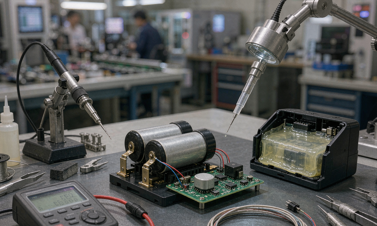
Potting compounds come in three families. Silicone (typically a two-part RTV) is flexible, repairable, has low exotherm during cure, and tolerates thermal cycling well. It bonds poorly to bare metal and is expensive. Epoxy (two-part, room-temp or heat-cure) is rigid, chemically resistant, and bonds well to almost everything, but it cannot be removed for repair, and the cure exotherm can damage temperature-sensitive components. Urethane sits in the middle — flexible, paintable, moderate bond strength. For most sensor packs with a microcontroller, radio, and a few passives, I specify a low-stress urethane or a flexible epoxy, vacuum-degassed before pour to eliminate voids around connectors.
A few production rules I enforce on every line. The two-part mix ratio must be within one percent — even a small deviation leads to incomplete cure and outgassing that corrodes the PCB over months. Mixers should be disposable static tubes, not reusable cups, and a fresh tube is logged against the lot number. For outdoor sensor modules, I always add a breathable Gore membrane vent to the enclosure. The membrane is hydrophobic, so liquid water and dust cannot enter, but air can pass to equalize pressure during temperature swings. Without it, the enclosure breathes around the seal and pulls moisture into the housing over years of thermal cycling. Conformal coating the exposed PCB before potting — HumiSeal 1A33 or Electrolube AFA is my default — protects any components that survive outside the potting compound.
Termination and Interconnect on the Line
The termination between cell and PCB is where I see the most field-failure root causes. Spot-welded nickel tabs of 0.10 to 0.15 mm thickness are the standard for primary lithium cells; I require a minimum of three weld dots per tab and a peel strength test exceeding five newtons. Ultrasonic aluminum wedge bonding at twenty-five micrometer wire is the right choice for miniature coin-cell tabs where spot welding cannot be controlled. Reflow soldering the cell directly to the PCB is acceptable only with cell chemistry and housing that can survive the two-hundred-sixty-degree reflow profile, which excludes most primary lithium cells with heat-sensitive seals.
PCB-to-host connectors are where I see the second-most field failures. JST PH and SH series are fine for indoor enclosures, but for any deployment where the cable enters a wet environment I specify IP-rated M8 or M12 connectors with O-ring sealing. Strain relief is non-negotiable. The cable exit needs either a silicone overmold, a hot-melt glue strain-relief boot, or a cable gland that grips the jacket. Polarization on the connector plus a color-coded wire plus a polarity dot silk-screened on the PCB saves far more service hours than the few cents it costs. Reverse polarity on a primary lithium pack is the most common battery-solution deployment error in the field I run.
In-Line and End-of-Line Tests
Every battery I ship goes through a sequence of tests, and every one of these is logged against the cell serial number. At cell receipt I do a hundred-percent open-circuit voltage check. For Li-SOCl2 I reject anything below 3.55 V; for Li-MnO2 coin cells anything below 3.0 V. A low OCV usually means a year on the shelf in uncontrolled temperature or a slow leak inside the cell.
After welding, each unit gets a DCIR pulse at a test fixture — 0.5 C rate for 100 ms — and I reject anything whose first-pulse minimum voltage drops below 3.0 V. That single test catches cold solder joints, weak welds, and cells with abnormally thick passivation layers. Insulation resistance on the finished pack is a hundred-percent test: five hundred volt megger, reject below one hundred megaohm. For IP67 and above, I add a leak test on a sample basis — helium mass spectrometry or pressure decay — at zero point one percent of the batch to validate the enclosure.
Burn-in is one hundred percent at fifty degrees Celsius for twenty-four hours and one percent of the batch for one hundred sixty-eight hours. Anything that survives burn-in is shipped. First-article units from every new production lot also go through a five-cycle duty-equivalent test before the line ramps. Date code and serial number are laser-etched onto the enclosure, never printed on a sticker — stickers fall off in three years of UV exposure, laser marks last the life of the product. Every test result is uploaded to a traceability database with the cell lot number, the production line ID, the operator ID, and the time stamp. That database is the first thing I pull when a field failure arrives at my desk.
Documentation, Compliance, and Traceability
The compliance stack for a custom battery solution for sensors depends on where it ships, who installs it, and how it is transported. UN38.3 is mandatory for any lithium battery moving by air freight, and most sea freight also requires it now. The eight tests cover altitude simulation, thermal cycling, shock, vibration, external short, impact, overcharge, and forced discharge. IEC 62133-2 is the cell-level safety standard required by most major OEMs and many jurisdictions; it covers drop, thermal abuse, and external short at the cell. UL 2054 is the household and commercial pack safety standard for North American retail channels. IEC 60079 plus ATEX directives are mandatory if the pack ships into hazardous-area zones on oil and gas or mining sites. RoHS and REACH declarations are needed for Europe, and California Proposition 65 requires its own labeling language.
Documentation is more than certificates. The cell lot traceability file lists the cell manufacturer, date code, and shipped condition. The pack-level documentation file lists the bill of materials, the production line, the operator, the test results, and the shipping carton. Every field return runs through a five-why analysis and the root cause is rolled back into the FMEA. After three of my customers sent back pack failures that traced to a single lot of nickel tabs with cold welds, I added inline weld-strength sampling on every lot. I have not seen that failure mode since.
Frequently Asked Questions
How long can a sensor battery module sit in storage before being installed?
For Li-SOCl2 bobbin cells, the practical shelf life is ten years at twenty-five degrees Celsius with annual self-discharge under one percent. Storage at forty degrees Celsius cuts that to about four years; at sixty degrees, two years. I always spec storage at ten to twenty-five degrees Celsius in the packaging label. The pre-conditioning pulse at the contract manufacturer guarantees consistent first-pulse voltage even after multi-year storage.
Can I use rechargeable Li-ion instead of primary lithium?
Only if the host system has a way to recharge the cell. A small 500 mAh Li-ion pouch plus a tiny BMS roughly quadruples the BOM of a primary pack, but it allows harvesting from solar, kinetic, or thermal sources. The trade is shorter calendar life — typically two to three years before noticeable degradation — versus ten-plus years for a primary. For remote sensors with no energy harvesting, primary Li-SOCl2 is almost always the better battery solution.
What is the right potting depth — full PCB or partial?
Full PCB potting is the most protective, but it makes the pack non-repairable and adds roughly thirty percent to the assembly cost. Partial potting — covering only the battery contacts and the connector area — leaves the microcontroller and radio accessible for rework but exposes those parts to condensation. For long-life outdoor sensors I use full PCB potting with a flexible urethane; for indoor short-life sensors I prefer partial potting to keep rework options open.
Do I need a UN38.3 test report for every battery?
UN38.3 is required for the cell, not the pack, and a single test report covers that cell model from that manufacturer. The report is valid for as long as the cell design and manufacturing process remain unchanged. If the cell manufacturer changes the separator, electrolyte, or anode, a new UN38.3 report is mandatory. The pack-level transport test under UN38.3.3 covers the pack in its shipping configuration and is the responsibility of the pack assembler.
What is a realistic cost per node for a Li-SOCl2 sensor pack?
At one hundred thousand units per year, a D-size Li-SOCl2 plus PCB plus IP67 enclosure plus urethane potting lands in the eight-to-fourteen dollar range depending on certification costs and connector quality. Volumes under ten thousand run higher because the tooling amortizes over fewer units. The bigger lever than unit cost is total cost of ownership across the deployment life — a cheaper pack that fails two percent early in the field is more expensive than a quality pack at thirty percent higher BOM.
How do I validate a new manufacturing partner before signing the PO?
Run a pre-production batch of fifty to one hundred units through the full test plan and verify the failure rate is under zero point five percent on first-article inspection. Visit the line and watch the operator execute the potting process — mix ratio, vacuum cycle, cure time. Ask for their cell traceability records on the last three lots they shipped. A manufacturer who cannot produce those records within an hour is not ready for your program. I always run a pilot of one thousand units before committing to the full annual volume.





