
Battery Solution Integration for Equipment: An Engineer’ (2)
When a finished battery solution leaves the bench and lands inside a host machine, the work is not over. Integration is where a pack that survived 200 cycles of validation either behaves like part of the equipment, or fights it. In the last ten years I have walked into factories, marine skids, and remote pumping stations to find packs that were specced correctly yet installed incorrectly: a missing precharge resistor that welds a contactor on every restart, a CAN cable run parallel to a VFD output for nine meters that wakes up the BMS at 2 a.m., a battery that survived the test bench but cooked because no one calculated the host enclosure’s thermal coupling. The good news is that integration is far more predictable than chemistry. There is a finite list of things that go wrong, a finite list of measurements to confirm them, and a finite list of paper artefacts to leave behind. This guide is the field-tested workflow I now hand to every junior engineer joining the integration team. It is written for lithium battery solutions going into stationary or mobile industrial equipment, and it is anchored in the same standards we use in our factory: UN38.3, IEC 62619, IEC 62133-2, UL 1973, and where relevant UL 9540A and NFPA 855.
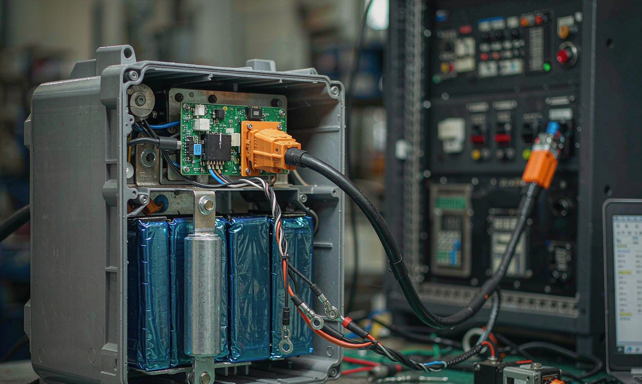
1. The Five Interfaces of a Battery Solution Integration
Before you lift the pack into place, sketch the host machine on paper and mark the five interfaces where the battery solution will meet the rest of the equipment. Miss any of them and the integration will haunt you for the life of the product.
- Mechanical interface: mounting feet, frame tolerances, CoG shift, vibration isolation, drip loops, and accessibility for service.
- Electrical power interface: bus voltage, contactor or fused disconnect, precharge, main breaker coordination, and short-circuit clearing.
- Thermal interface: heat-sink coupling, air gap, coolant loop taps, ambient sensor placement, and cold-start behavior.
- Data interface: CAN bus or RS-485, baud rate, register map, fault frames, isolation, and termination.
- Safety interface: emergency stop loop, HVIL, pyrofuse, fire suppression signal, and grounding.
Treat each interface as a contract. Every connector on the drawing is either a defined point of integration or a future rework item. The first ten minutes of an integration project, spent walking the host with the OEM drawing, save ten hours of rework in the field.
2. Mechanical Integration: Mounting, CoG, and Service Access
Mechanical integration is the easiest interface to underestimate. The most common failure mode I see on industrial battery solution integration jobs is not a broken cell but a broken mount after eighteen months of vibration. Three rules cover ninety percent of cases.
Mount on stiff structure, not panels. Mounting feet should land on machined bosses welded to the main frame, never on a sheet-metal panel or a cosmetic cover. Panels flex; frames don’t. If the only available surface is a panel, add a backing plate that ties to two adjacent frame members. A 100 Ah pack can reach 25 kg, and at 5 to 500 Hz random vibration that mass multiplies every loose fastener into a fatigue crack within a year.
Respect the center of gravity. A battery that weighs 25 kg placed 200 mm above the host’s original CoG can change handling dynamics enough to flip a counterbalanced machine. For mobile equipment, measure the new CoG with a weighbridge before and after, and update the operator’s manual. For stationary cabinets, calculate the overturning moment against the seismic or wind load if the cabinet is taller than 1.5 m.
Service access is non-negotiable. Every bolted cover, every cell, every contactor, every fuse, and every connector must be reachable with the standard tool kit specified for the host. If the only way to swap a contactor is to remove the pack from the cabinet, the contactor will not get swapped; it will get bypassed. I have seen bypassed contactors in 35 kWh marine skids that should have been replaced for $80, costing $35,000 in warranty.
Use M6 stainless steel fasteners for general mounting and M8 or M10 for high-stress joints. Torque per ISO 16047 with a calibrated tool. Mark each fastener with a paint pen after torque, so a visual inspection at quarterly service reveals any drift. M6 lands at 8 to 10 N·m, M5 at 4 to 6 N·m, M8 at 12 to 14 N·m. These numbers are not negotiable; they are the line between a battery solution that stays in place and one that walks itself out of the cabinet.
3. Electrical Power Integration: Precharge, Fusing, and Breaker Coordination
Electrical integration is where engineers with strong software skills and weak power-electronics skills hurt themselves. The single most common mistake is omitting the precharge circuit. When a lithium pack powers a DC bus that includes inverter or motor-drive capacitance, closing the main contactor onto a discharged bus causes an inrush that welds the contactor contacts within ten cycles. I have replaced more contactors due to missing precharge than for any other cause combined.
Precharge rule: if the host DC bus capacitance is greater than 1000 µF and the pack voltage is above 48 V, install a precharge resistor sized to limit the inrush to under 30 A and to bring the bus to within 5 percent of pack voltage within 500 ms. A 100 Ω, 50 W resistor in series with a small auxiliary relay handles most sub-400 V packs. For systems above 400 V, scale the resistor to 220 Ω and use a 100 W rated part to keep the surge thermally benign.
Fuse coordination: the main fuse must clear a bolted short on the load side before the contactor opens. Use DC-rated fuses with an AIC at least 1.5 times the available short-circuit current of the pack, and never reuse AC-rated breakers on a DC bus above 60 V. For 48 V systems a 1000 A DC fuse is a sensible starting point; for 400 V packs, work backward from the DCIR of the cells and the loop inductance to size the fuse I²t below the cell’s thermal runaway energy.
Grounding and bonding: the battery enclosure should bond to the host chassis with a dedicated ground strap, not rely on the mounting bolts alone. Paint and anodizing create high-impedance joints that defeat fault clearing. Use a tinned copper braid, 16 mm² minimum, and torque the ground lug to 6 to 8 N·m onto a bare-metal boss. Verify with a four-wire milliohm meter that the chassis-to-pack resistance is below 1 mΩ after the paint is scraped off.
Harness routing: separate the high-current cabling from the signal and data cabling by at least 150 mm, or cross them at 90 degrees. Run the HV cable through grommets and add drip loops at every low point so condensation does not track into the connector. A drip loop is not decorative; it is the cheapest insurance against field failure in an outdoor or marine installation.
4. Thermal Integration: Sensor Placement and Air-Coupling
Thermal integration is the silent killer of lithium battery solutions. A pack that runs at 35 °C ambient will live twice as long as the same pack at 45 °C ambient; the Arrhenius rule of thumb is that every 10 °C doubles calendar aging for LFP and nearly triples it for NMC. The most expensive mistake I see is locating the temperature sensor on the outside of the enclosure instead of on the hottest cell surface inside.
Sensor placement: install at least one thermistor on a cell surface in the geometric center of the pack, and a second on a cell at the end of the busbars where current crowding raises the temperature 3 to 5 °C above the average. Adhesive-mount the sensor with thermally conductive epoxy, not silicone, and insulate it from the cold side with a foam pad so the measurement reflects cell heat, not air temperature. Connect both thermistors to the BMS, and configure the BMS to derate charge current above 45 °C and to disconnect above 60 °C on either sensor.
Air coupling: for passively cooled packs, leave a 20 mm air gap on every face that is not a mounting surface, and route the host’s cooling air along the cell faces, not across the BMS. For active cooling, calculate the pressure drop across the pack at the host’s nominal fan curve; a 25 Pa pressure drop can quietly halve the airflow a fan was sized to deliver. If you need a fan, add a tachometer feedback to the BMS so a stalled fan triggers a fault instead of a slow cook.
Cold-start: lithium cells cannot accept charge below 0 °C without risking plating. If the host operates outdoors in cold climates, either add a heating pad sized to 30 to 60 W per kWh, sized to warm the pack from −20 °C to 5 °C in under 90 minutes, or interlock the contactor so charge current is blocked until the pack temperature rises above 2 °C. The interlock is cheaper, but the heating pad extends runtime and avoids a stranded machine at dawn.
5. Data Integration: CAN, RS-485, and the Register Map
A battery solution that does not talk to its host is a battery solution that is going to be blamed for every fault in the system. The data interface is the contract that lets the host treat the pack as a smart peripheral rather than a black box. Two physical layers dominate industrial equipment: CAN 2.0B at 250 or 500 kbaud, and RS-485 Modbus RTU at 9600 or 19200 baud. Both work; neither is universally preferred.
CAN is the default for mobile equipment and most modern machines because it survives electrical noise better and supports multi-drop topologies without an extra gateway. The price is a closed register map that both sides must agree on. At minimum, broadcast the pack voltage, pack current, state of charge, state of health, cell temperature, and a 16-bit status word that includes over-voltage, under-voltage, over-temperature, communication timeout, and precharge complete. Update the status word at 10 Hz; broadcast SoC and voltage at 1 Hz; log events at the moment they occur.
Modbus is the default for SCADA-integrated stationary equipment, where long cable runs and existing RTU infrastructure favor RS-485. The trade-off is half-duplex polling, which means the host can only ask for one register at a time. Use Modbus only for slowly varying values: voltage, current, SoC, SoH, and alarms. Do not try to push event logs over Modbus; the bandwidth is wrong.
Isolation is mandatory. Whatever physical layer you choose, isolate the transceiver on the battery side with a 3 kV reinforced isolator. A ground loop on a long cable run can lift the CAN reference by tens of volts and either destroy the transceiver or wake the BMS at random. I have seen a $0.30 isolator save a $4,000 service call.
Termination: a CAN bus needs 120 Ω termination at both ends. Add a switchable termination inside the pack so that the integrator can enable or disable it based on the bus topology. A bus that is double-terminated is hard to diagnose; it will run at half the expected speed and produce intermittent errors that read as “battery fault” on the host.
Before leaving the site, request a screenshot of the host’s CAN trace or Modbus poll log showing the pack IDs, voltages, and a known load event. That single file is the proof of integration and the first line of defense against future warranty disputes.
6. Safety Interface: HVIL, E-Stop, and Pyrofuse
The safety interface is non-negotiable. Every modern battery solution ships with a high-voltage interlock loop, a hardware emergency stop input, and increasingly a pyrofuse for fast short-circuit clearing. The host must wire all three into its safety chain, not just one of them.
- HVIL: a low-current loop through every HV connector that breaks whenever a connector is unmated. Wire the loop to the BMS so the contactors open within 100 ms of a break. Test the loop end-to-end at commissioning by pulling one connector; if the pack does not de-energize in under 100 ms, the integration is not complete.
- E-stop: hard-wire the host’s emergency stop circuit to the BMS enable input. The E-stop must open the contactors and latch them open until a manual reset. A BMS that resets itself after a few seconds defeats the entire safety chain.
- Pyrofuse: for systems above 400 V or above 50 kWh, install a pyrofuse on the main contactor line and trigger it from a dedicated BMS channel that monitors cell temperature and voltage simultaneously. A pyrofuse fires in under 5 ms and is the only device that can interrupt a developing internal short before the cell goes into thermal runaway.
Document the safety interface in a one-page diagram that the OEM keeps with the machine manual. The diagram should label every wire, the connector pin, and the test procedure. Six months from now, a service technician will pull a connector and need to know whether the pack will de-energize; the diagram is the answer.
7. The Commissioning Sequence: From Bench to Production
Commissioning is the test that proves the integration works as a system. I run the same sequence on every job, regardless of chemistry or size. The sequence takes about 90 minutes for a stationary pack and 3 hours for a mobile machine. Skip a step, and the step will come back as a warranty claim.
- Visual and mechanical: confirm all fasteners torqued and paint-marked, all connectors fully mated with locking tabs engaged, all drain holes and vents clear, and all labels affixed.
- Insulation resistance: with the contactors open, apply a 500 V megohmmeter between the HV bus and chassis ground. Reading must exceed 1 MΩ. Below 500 kΩ is a red flag; the pack goes back to the bench.
- Auxiliary supply: power the BMS from its 12 V or 24 V supply and confirm communication on the data bus. Read the BMS firmware version and record it on the acceptance sheet.
- Precharge test: command the BMS to close the precharge relay; measure the bus voltage on the host side. It must rise to within 5 percent of pack voltage within 500 ms. If it does not, the precharge resistor is undersized or the bus capacitance is higher than expected.
- Main contactor close: command the BMS to close the main contactor; confirm with a current probe that the inrush is under 30 A and decays within 200 ms.
- DCIR baseline: apply a 0.5 C pulse for 10 seconds; record the voltage drop and compute DCIR. Compare to the bench baseline. Drift above 15 percent indicates a connection problem inside the pack, not a cell problem.
- Light load: apply a 10 percent rated load for 5 minutes; record temperature rise, BMS SoC accuracy, and any fault flags. SoC error above 5 percent at this point is normal for a fresh pack and will improve with cycling.
- Rated load: apply 80 percent rated load for 15 minutes; record the same parameters plus contactor temperature and bus voltage sag. Sag above 5 percent at rated load is acceptable; above 10 percent is a sign that the cable gauge is too small.
- Hot shutdown: command the host E-stop and confirm the contactors open within 100 ms and latch open. Reset only after manual intervention.
- Documentation: save the data logs, take a photo of the installed pack, and update the asset register with the commissioning date and the acceptance test results.
For mobile equipment, add two more steps: a 30-minute road test under real load, and a vibration check that walks the entire operating envelope. For stationary equipment, add a 24-hour float test at 100 percent SoC and a one-week soak test with weekly logging.
8. Handover and Documentation
The handover is the moment a custom battery solution becomes the customer’s equipment. Five artefacts must leave with the machine.
- Battery datasheet: pack voltage, capacity, chemistry, weight, dimensions, connector pinout, fuse ratings, and operating temperature range.
- CAN or Modbus register map: every register, its scale factor, its units, and its update rate. Include a sample trace file from commissioning.
- Acceptance certificate: signed by both parties, with the commissioning test results attached.
- Service manual: torque values, recommended inspection intervals, replacement parts list, and contact information for warranty support.
- Training record: a sign-off sheet showing that the customer’s operators and service technicians have been trained on the E-stop, the HVIL, and the data interface.
Store all five in a folder named with the asset serial number and date. Cloud backup is mandatory; a USB stick in a drawer is not a handover. When the customer’s first service call comes in eighteen months, the file is the difference between a 30-minute phone fix and a two-day site visit.
9. Frequently Asked Questions
How long should commissioning take for a 50 kWh industrial battery solution?
Plan 3 to 4 hours including the soak test. A 100 kWh system takes 5 to 6 hours. Rushing the sequence to save half a day is the most expensive shortcut in the integration business; it always returns as a warranty event.
Do I need a precharge circuit for a 24 V or 48 V system?
If the host bus capacitance is below 1000 µF and the contactor is rated for the inrush, you can skip precharge. Above 1000 µF, install precharge regardless of voltage. The contactor does not care about voltage; it cares about inrush energy.
What is the most common cause of integration failure in the first six months?
Loose fasteners, in that order. Every other failure mode is a distant second. A quarterly torque check with a paint pen costs almost nothing and eliminates the largest single class of warranty claims on industrial battery solutions.
Can I use the same CAN register map for every customer?
Yes, and you should. A standard register map reduces engineering cost, allows a single BMS firmware across products, and lets your service team troubleshoot every pack in the field with the same tool. The map should include a “pack serial number” register so the data log identifies the unit.
What standards should I list on the integration certificate?
At minimum: UN38.3 for transport, IEC 62133-2 for cell safety, IEC 62619 for industrial lithium cells, and UL 1973 for stationary storage. Add UL 9540A and NFPA 855 if the installation is above 50 kWh or indoors. The certificate is also the place to list any local codes you followed.
Is it safe to integrate a battery solution into a host that has its own UPS?
Yes, but coordinate the grounding and the E-stop chain carefully. The host UPS should not backfeed the battery solution during a grid outage; otherwise the battery may be asked to power the UPS indefinitely and run to deep discharge. A simple interlock relay on the UPS output that opens when the pack contactor opens solves the problem at the cost of a $20 relay.
10. Closing Note from the Bench
Integration is the discipline of turning a battery into part of a machine. The work is unglamorous, the tests are repetitive, and the documentation is the part no one wants to write. And yet, every pack that fails in the field fails because someone skipped a step in this playbook, not because the chemistry let them down. Run the sequence, sign the certificate, train the customer, and the battery solution will deliver the eight to twelve years of service it was designed to give. That is the entire job.





