
Battery Solution Performance for Robotics: Peak-Power
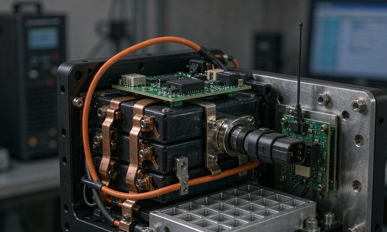
When procurement teams ask me how to evaluate a battery solution performance robotics spec sheet, I always tell them the headline capacity number is the least interesting figure on the page. What actually decides whether an autonomous mobile robot (AMR), automated guided vehicle (AGV), or humanoid fleet pays back its capital is how the pack behaves during the worst 200 milliseconds of every drive maneuver — the peak-power transient — and how cleanly it absorbs the regenerative pulse when the drive motors brake. After fifteen years building lithium battery packs for warehouse, manufacturing, and service robotics customers, I have learned that the battery solution performance robotics buyers care about is a dynamic metric, not a static one. In this article I will walk through the three engineering criteria I use in every customer review: peak-power transient response, regenerative braking charge acceptance, and fleet telemetry benchmarks that prove the lab numbers actually survived the warehouse floor.
Why Peak-Power Transients Define Real Battery Solution Performance for Robotics
The first time I watched an AMR customer write off a pack supplier, it was not because the cell datasheet was wrong. The supplier had delivered a 48 V, 60 Ah LiFePO4 pack rated for 1.5 kW continuous discharge, and the AMR accelerated fine on the showroom floor. Two weeks into production deployment, the customer noticed that every time three robots converged at a picking station and started their lift actuators simultaneously, the fleet management software logged a low-voltage brownout. The robots stopped, rebooted, and waited thirty seconds for the supervisory controller to clear them — a forty-thousand-dollar monthly productivity loss in a single shift.
The root cause was straightforward physics. Three lift actuators drawing 90 A each for 250 ms produced a 270 A pulse, well above the 125 A continuous rating and even above the 200 A 10-second rating on the datasheet. The voltage sag under that pulse was 5.2 V, dropping the bus from 48 V to 42.8 V — below the 44 V brownout threshold the robot OEM had configured to protect its drivers. From a battery solution performance robotics standpoint, the pack had failed because the supplier had not characterized pulse impedance at the actual working SoC (40–60 %) and at the cold-soak temperature (8 °C) of the warehouse, not the 25 °C test bench.
For buyers evaluating a battery solution performance robotics claim, my engineering rule is simple: demand a pulse profile that looks like the robot, not like a hybrid electric car. A 10 C, 10-second test at 25 °C tells you almost nothing about whether the pack will survive a 5 C, 0.25-second pulse at 10 °C. I ask suppliers to deliver at least three pulse characterization curves: one at 25 °C / 50 % SoC, one at 10 °C / 50 % SoC, and one at 25 °C / 20 % SoC. If the supplier cannot produce those, I treat the pack as untested for the application.
Regenerative Braking Charge Acceptance and Why Most AMR Packs Under-Use It
The second and often more underrated dimension of battery solution performance robotics is regenerative braking charge acceptance. When an AMR or AGV decelerates from a 2 m/s cruise to a 0 m/s stop at a charging dock, the drive motor becomes a generator. The energy that would otherwise be burned as heat in the brake resistors flows back into the lithium battery pack as a charging pulse. The energy is small in absolute terms — typically 20 to 80 Wh per stop depending on the robot mass and speed profile — but over a fleet operating 200 stops per shift, the recovered energy runs into single-digit kWh per robot per day. Across a 200-robot fleet that is a non-trivial number on the utility bill, and it extends the cycle life of the pack because each recovered Wh corresponds to less depth-of-discharge stress on the cells.
Where most AMRs under-use regeneration is at the cell-and-BMS interface. A standard CC/CV lithium charge profile assumes a 0.5 C maximum charge current, which is fine for overnight opportunity charging but completely wrong for capturing regen pulses that arrive unpredictably and demand 1.5–2.5 C acceptance for under a second. If the BMS treats the regen pulse as an over-current event and disconnects the pack, the energy is dumped into the brake resistor and the operator sees zero fuel savings. The battery solution performance robotics specification has to call out the maximum regen pulse acceptance explicitly, in amps and in milliseconds, and the BMS firmware has to be configurable to allow it without tripping protection.
In the cells themselves, charge acceptance under a 1.5 C pulse is dominated by the anode kinetic window. LiFePO4 cells typically accept 2 C pulses without a measurable voltage rise, while NMC cells start to hit lithium-plating risk around 1.2 C if SoC is above 85 %. For AMR applications where the pack rarely operates above 90 % SoC, both chemistries can work, but the BMS SoC window has to be tuned accordingly. I have shipped both LiFePO4 and NMC packs for AGV applications and the practical answer is usually LiFePO4 for cycle life, NMC only when the customer demands minimum pack volume.
Fleet Telemetry Benchmarks: The Proof Layer Behind Battery Solution Performance Robotics
The third pillar of a serious battery solution performance robotics program is fleet telemetry. A pack that performs well on the HIL bench can still fail in production because of cell-to-cell variance, connector wear, or BMS firmware drift across hundreds of robots. The only way to know what is actually happening on the floor is to instrument every pack with a telemetry uplink — minimum cell-voltage tap on every series group, pack current via a Hall sensor, pack temperature at three locations, and SoH/SoC estimation pushed to a cloud endpoint at least once per minute. The supplier’s responsibility does not end at the connector; it extends to defining the dashboard that the fleet operator will use to triage robots before they fail.
The benchmark that I have found most predictive in practice is what I call the Delta-V95 — the 95th-percentile of the cell-to-pack voltage spread over a representative shift. In a healthy pack, Delta-V95 sits below 25 mV at rest and below 40 mV under a 1 C pulse. When Delta-V95 starts climbing past 60 mV on rest and 90 mV under pulse, it is the early signature of an internal resistance imbalance that will, within 60 to 120 days, become a hard cell failure on a robot during a customer shift. Catching that climb on a dashboard and replacing the pack under planned maintenance is dramatically cheaper than catching it as a 2 AM field-service call.
For procurement teams writing an RFP, I recommend asking for three concrete deliverables tied to battery solution performance robotics telemetry. First, a sample API endpoint showing the payload format the supplier uses in production today. Second, a one-year retention guarantee on the telemetry archive at minimum 1-minute resolution, with export to CSV or Parquet. Third, a quarterly business review format that includes a fleet-wide reliability report stratified by robot model, shift, and route. Any supplier who cannot produce all three is, in my experience, selling cells and enclosures rather than a battery solution.
Standards, Certifications, and What They Mean for Battery Solution Performance Robotics in Practice
Battery solution performance robotics specifications always live inside a regulatory envelope, and the envelope varies by deployment region and by application. For warehouse and manufacturing robots in the United States, the relevant safety standards are UL 1973 for stationary cell-level certification, UL 2271 for the light-rail and mobility-pack overlap category, and UN 38.3 for the transport classification that every lithium pack has to clear before air or sea freight. In the European Union, IEC 62619 covers industrial lithium cells, IEC 62133-2 is the portable secondary cell standard, and EN 1175 governs the electrical safety of battery-powered trucks and their chargers.
For service robotics that operate near people — delivery robots, hospital logistics AMRs, and humanoids — IEC 61508 SIL-2 functional safety and ISO 13849-1 PL d are increasingly being written into customer RFQs because the BMS has to behave predictably not only in normal operation but also under fault conditions. I treat these functional-safety requirements as part of battery solution performance robotics because they directly constrain how the BMS firmware can respond to fault events: a pack that brownouts on a transient is a safety event, not just a productivity event, when a robot is carrying medical supplies through a public corridor.
My practical checklist for buyers is: UN 38.3 transport report, IEC 62133-2 or UL 1973 cell-level certificate, IEC 62619 pack-level certificate for industrial deployments, and a documented EMC test report to EN 61000-6-2 / EN 61000-6-4 covering both radiated and conducted emissions. If the supplier hands you only the cell-level certificate, ask for the pack-level certificate before signing the PO — there is a meaningful difference between cell compliance and pack compliance, and it is the pack that gets installed in your fleet.
Engineering Trade-Offs That Buyers Should Understand Before Specifying a Pack
Battery solution performance robotics is fundamentally a multi-objective optimization, and the trade-offs deserve explicit discussion in the supplier conversation. Energy density versus power density is the classic trade-off — NMC at 240 Wh/kg and 3 C continuous versus LiFePO4 at 160 Wh/kg and 5 C continuous — and the right answer depends on whether the robot’s bottleneck is shift duration or peak power. For warehouse AMRs that run two eight-hour shifts with mid-shift opportunity charging, LiFePO4 is almost always the right answer because the lower energy density is more than offset by the higher cycle life (typically 4,000–6,000 cycles at 80 % DoD versus 1,500–2,500 for NMC). For humanoid robots that need to pack 1.5 kWh into a 4-liter volume, NMC at a conservative 70 % SoC window is usually unavoidable.
Cooling architecture is the second trade-off that defines battery solution performance robotics outcomes. Passive convection works for low-duty AGVs but fails for fast-cycling AMRs that see 1 C charge and 1 C discharge every 90 seconds. Liquid cold plates tied to the robot’s existing coolant loop are the gold standard, and I recommend specifying the coolant interface (typically -5 °C to +45 °C coolant supply at 1.5–3 L/min) in the pack spec sheet rather than leaving it to the robot OEM. Forced-air cooling is the middle ground and works in moderately clean environments, but in dusty or humid warehouses it pulls particulates through the cells and accelerates connector wear.
Cell format — cylindrical 21700, prismatic, or pouch — is the third trade-off and the one that tends to surprise procurement teams the most. Cylindrical cells offer the best mechanical robustness and the easiest cell-to-pack serviceability, but they pack at a lower volumetric density. Prismatic cells hit the volumetric sweet spot for most robotics form factors. Pouch cells maximize energy density but require compression frames and are difficult to field-service. I default to prismatic for AMR/AGV and cylindrical for service robotics where field-serviceability matters; I rarely ship pouch cells to robotics customers because the failure modes under vibration tend to dominate the value proposition.
Frequently Asked Questions About Battery Solution Performance Robotics
What is the single most important spec to ask a battery supplier about for an AMR fleet?
Ask for the cell-to-pack voltage spread under a 1 C pulse at 25 °C and 50 % SoC, measured in millivolts across all series groups, on at least five production packs from the supplier’s last shipping batch. Anything above 40 mV indicates a pack-to-pack variance that will translate directly into fleet-level reliability risk. This single metric tells you more about battery solution performance robotics outcomes than capacity, C-rate, or cell chemistry combined.
How does regenerative braking really extend pack life in AMR applications?
Every regen pulse that the pack successfully absorbs reduces the depth of discharge the cells experience on the next acceleration cycle, and reduced DoD is the single strongest predictor of lithium cycle count. Capturing 5–8 % of the operating energy as regen over a full shift is realistic in well-tuned fleets, and that translates to roughly 1.5× to 2× cycle-life extension in field data. It also reduces battery solution performance robotics thermal stress because the cells spend less time at high SoC where calendar aging accelerates.
Should I specify LiFePO4 or NMC for a new robotics program?
Specify LiFePO4 unless the robot’s mechanical envelope physically cannot accommodate it. LiFePO4 offers 2–3× the cycle life of NMC at comparable cost, accepts regen pulses more cleanly, and has a far better thermal-abuse safety margin. NMC wins only when volumetric energy density is the binding constraint, which is typically the case only for humanoid robots and small-format service robots. For warehouse and manufacturing AMRs/AGVs, LiFePO4 is almost always the correct answer.
How often should I review fleet telemetry for battery health?
Review weekly at the fleet level, looking at Delta-V95 and pack impedance trends across the population, and review individual robots monthly against their own baseline. Any pack that shows a 15 % or greater impedance rise month-over-month should be flagged for planned replacement before it fails on shift. Battery solution performance robotics reliability is fundamentally a statistical exercise, and the dashboard review cadence has to match the failure rate you are willing to tolerate.
What standards should be on the supplier’s certificate list?
Minimum: UN 38.3 for transport, IEC 62133-2 or UL 1973 for cells, IEC 62619 for industrial packs, and EN 61000-6-2 / EN 61000-6-4 for EMC. For service or human-adjacent robots, add IEC 61508 SIL-2 functional safety documentation and ISO 13849-1 PL d for the BMS safety functions. Anything less than this list signals a supplier who has optimized for cost rather than for production reliability.
Can I retrofit telemetry into an existing fleet?
Yes, but it is rarely cost-effective below a 50-robot fleet. Battery solution performance robotics telemetry works best when it is designed in from the supplier’s BMS rather than retrofitted with an aftermarket shunt and gateway, because the BMS already knows the cell-level voltages and the SoC state machine. For smaller fleets, a quarterly field-service battery health check using a portable impedance tester is usually a better return on engineering time than a retrofit telemetry deployment.





