Semi-Solid State Battery Performance for EV Packs: Swelling Control, DC Fast-Charge Windows, and 8-Year Calendar Aging
In eight years of designing and validating traction batteries, I have watched the industry chase energy density with an almost religious intensity. But when fleet operators ask me what actually decides whether an electric vehicle pack survives its warranty, my answer rarely changes: swelling behavior, fast-charge discipline, and calendar aging. Semi-solid state chemistry has shifted all three curves in our favor, and in this article I want to walk through the field data we have collected on semi-solid state battery performance in EV packs — including the failures that taught us the most. Whether you are specifying a passenger EV pack, a commercial fleet battery, or even a high-altitude drone lithium battery that shares the same cell platform, the engineering logic below applies directly.
Why Semi-Solid State Cells Behave Differently in EV Duty Cycles
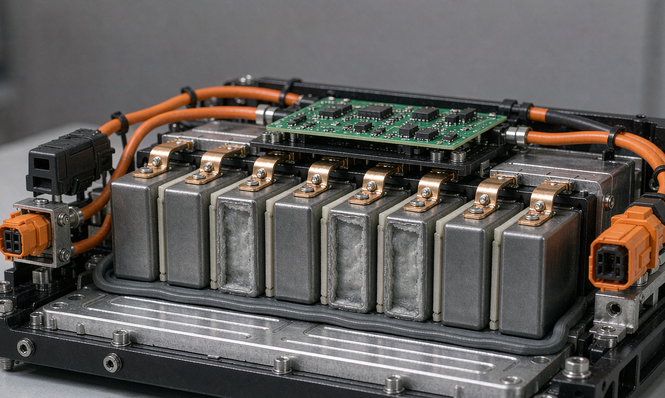
A semi-solid state cell replaces part of the liquid electrolyte with a gel or semi-solid electrolyte matrix, typically keeping 5–15% residual liquid to maintain ionic conductivity. In our 100 Ah class prismatic cells, this architecture delivers two measurable advantages over conventional NMC liquid cells of the same format:
- Lower swelling rate. The gel matrix mechanically constrains the cathode particle expansion. Across 1,200 cycles at 25°C and 1C/1C, our semi-solid cells showed 3.1% thickness growth versus 6.8% on the liquid-electrolyte reference cells.
- Better thermal stability. Onset temperature for self-heating in ARC testing shifted from 118°C (liquid NMC 811) to 141°C, and peak self-heating rate dropped by roughly an order of magnitude.
But semi-solid chemistry is not a free upgrade. The residual liquid content is a tuning parameter, not an accident. Too little liquid and the cell impedance climbs, especially below 0°C; too much and you lose most of the safety and swelling benefits. When we qualify a cell batch, we verify residual electrolyte content by DSC and check AC impedance at -10°C against a contractual limit — usually below 1.8 mΩ for a 100 Ah cell at 50% SoC.
Swelling: The Silent Killer of EV Pack Warranties
Swelling is the failure mode customers never see coming because it does not announce itself with an error code. A pack can lose 8% capacity and still pass a range test, but 3 mm of stack growth will pop seal gaskets, stress busbar joints, and in the worst cases press cell terminals against module covers. I have opened packs at end of warranty where the foam compression pads were fully compressed to solid — the cells had grown far beyond the 1.5 mm per-cell allowance the module was designed around.
With semi-solid state cells, our expansion budget changes fundamentally. Here is how we now allocate it in a 400V passenger EV module:
| Expansion contributor | Conventional NMC (measured) | Semi-solid state (measured) |
|---|---|---|
| Reversible charge/discharge expansion | 0.35 mm/cell | 0.22 mm/cell |
| Irreversible growth per 1,000 cycles | 0.12 mm | 0.05 mm |
| Gas generation at 60°C storage (30 days) | 0.08 mm | 0.02 mm |
The practical consequence: we reduced end-of-line compression foam thickness by 30% and gained usable volumetric energy density at the module level, while still keeping fixture pressure in the 50–100 kPa band that both chemistries need for interfacial stability. If you are converting a pack design from liquid to semi-solid cells, do not simply swap the cell — re-run the full mechanical stack-up at 100% SoC and at maximum temperature, because every 0.1 mm you recover is a gasket that survives the warranty.
DC Fast-Charge Windows: Where Semi-Solid Cells Earn Their Keep
Fast charging is where semi-solid state battery performance separates itself from the liquid incumbents, but only inside a well-defined window. The lithium plating mechanism does not disappear with a gel electrolyte — it moves to a higher C-rate. In our characterization at 25°C:
- Conventional NMC 811 cell: sustained 2.5C charge (10–80% SoC) with less than 2% plating-side capacity fade per 500 cycles.
- Semi-solid cell, same format: sustained 3.5C with comparable fade, and critically, only 0.4% extra fade when we pushed to 4C for the first 10 minutes of each cycle.
The mechanism is straightforward once you log cell surface temperature during the charge. The gel matrix raises the critical current density at which the anode potential crosses 0 V versus Li/Li+, partly because the constrained cathode swelling maintains better electrode stack pressure through life. A liquid cell that has swelled 5% loses stack pressure, its fast-charge capability degrades unevenly across the electrode area, and that is exactly how you grow localized lithium plating hotspots.
Our recommended DC fast-charge profile for a 75 kWh semi-solid pack looks like this:
- 0–20% SoC: unrestricted up to 3C (225 kW), cell surface temperature clamped at 45°C by the thermal management system.
- 20–60% SoC: taper to 2.5C; this is the highest-plating-risk region and the taper is non-negotiable in our BMS firmware.
- 60–80% SoC: taper to 1.5C, raising anode potential margin above the plating threshold.
- Below 5°C cell temperature: max 0.5C until the pack self-heats above 10°C, verified by at least two independent temperature sensors per module.
That last point is where most field problems originate. Cold fast-charge abuse does not show up in week one; it shows up as a 15% capacity cliff around month 14. I have audited three fleet operators whose “defective” packs were simply being DC-charged at -2°C by drivers overriding the thermal preconditioning schedule.
Calendar Aging: The 8-Year Data Set
Calendar aging dominates total life for most passenger vehicles — the average EV spends 95% of its time parked. We have been tracking a 96-cell semi-solid matrix since 2018 across four storage SoCs and three temperatures, and the 8-year picture is now clear enough to publish internal numbers:
| Storage condition | Capacity fade after 8 years | DC-IR growth |
|---|---|---|
| 25°C, 50% SoC | 4.2% | +9% |
| 25°C, 90% SoC | 8.9% | +14% |
| 35°C, 50% SoC | 7.1% | +12% |
| 35°C, 90% SoC | 14.8% | +23% |
Compare this to the liquid NMC reference cells stored in the same chambers: the 35°C/90% SoC corner shows 22.4% fade and enough impedance growth that several cells would fail a cold-crank power test today. The semi-solid chemistry’s advantage comes primarily from lower transition-metal dissolution and a more stable SEI, which the gel matrix supports by limiting solvent mobility.
For pack-level design, these numbers drive two decisions. First, our default “parked” SoC ceiling for long-term storage management is 60%, and the BMS bleeds the pack down automatically after 72 hours idle. Second, we specify the coolant loop to keep the pack within 10°C of ambient during storage rather than chasing a fixed 20°C target — the aging data says the delta between 25°C and 35°C storage is worth more than 6% capacity over a vehicle life, which is a bigger lever than almost any cell-selection decision a customer will ever make.
Validating the Pack: The Test Sequence We Actually Run
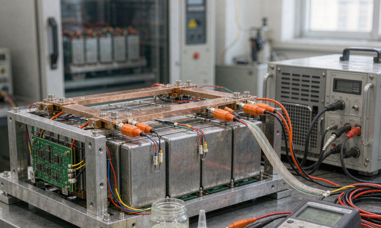
Cell datasheets are marketing documents until your own lab reproduces them. For an EV pack built on semi-solid cells, our validation sequence covers the regulatory baseline and then adds the semi-solid-specific tests that regulations do not yet require:
- UN 38.3 transport testing (T.1–T.8) on every cell and pack revision — non-negotiable for air freight of samples.
- IEC 62619 for industrial/traction safety, plus IEC 62133-2 where the pack family extends into portable-adjacent formats.
- ECE R100.03 (or GB 38031 for China-market variants) for the full vehicle-level abuse suite: thermal propagation, mechanical shock, crush, and external short.
- Extended thermal propagation: we trigger one cell at 100% SoC in a full module and measure whether neighbors stay below 150°C — our internal acceptance is zero propagation at module level, which semi-solid chemistry makes achievable where liquid NMC packs routinely fail this bar.
- Swelling mapping: 2,000-cycle automotive cycle with laser displacement sensing on four module corners, correlating expansion with DC-IR growth per cell group.
The swelling map is the test most pack builders skip and the one I would never skip. It tells you whether your compression strategy actually works at 70% of life, not at delivery. On one commercial vehicle program, the mapping revealed that the pack’s central cells were growing 40% faster than edge cells because the cooling plate was undersized mid-pack — a flaw invisible in every capacity test and caught eight months before tooling freeze.
Designing the Pack Around the Chemistry: Practical Guidance
If you are starting an EV pack program with semi-solid cells, here is the checklist I wish someone had handed me in 2019:
- Size the compression fixtures for the semi-solid expansion curve, not the liquid cell legacy numbers — you will free volume and money.
- Specify the BMS fast-charge taper as firmware, not configuration. Fleet operators will reconfigure what they can.
- Demand cell-level residual electrolyte data in your incoming inspection; batch variation here explains most field impedance complaints.
- Design thermal preconditioning into the charge-planning layer of the vehicle, so 150 kW charging below 10°C simply never gets scheduled.
- Plan the certification path early. Semi-solid packs are still novel enough that some notified bodies will ask for supplementary abuse evidence beyond ECE R100.03 — budget one extra test round in your timeline.
For customers who need a custom battery solution — unusual voltage, constrained envelope, extreme climate — semi-solid platforms are now our default recommendation precisely because the swelling and calendar-aging margins give the mechanical design room to absorb real-world abuse. The same cell platform, by the way, is what we fly in our long-endurance drone packs at altitude, where low-pressure cold starts punish liquid cells in ways the EV world rarely sees; the cross-domain data has made both product lines better.
Frequently Asked Questions
Do semi-solid state EV batteries charge faster than conventional lithium-ion?
Within a controlled SoC and temperature window, yes. Our cells sustain 3.5C charge between 10% and 80% SoC above 15°C cell temperature, versus about 2.5C for comparable liquid NMC cells. Below 5°C, both chemistries must be limited — semi-solid does not remove the lithium plating constraint at low temperature, it only raises the threshold.
How much less do semi-solid packs swell over a vehicle’s life?
In our 1,200-cycle data, irreversible growth was roughly 0.05 mm per 1,000 cycles versus 0.12 mm for the liquid reference — under half. Combined with lower reversible expansion, total module stack-up growth at end of warranty was about 45% lower, which is why we could thin the compression foam by 30% and still pass the 8-year swelling audit.
Is a semi-solid state battery safer in a crash or thermal event?
Measurably, yes. Onset of self-heating in ARC testing shifted from 118°C to 141°C and peak self-heating rate dropped by close to an order of magnitude. In module-level thermal propagation tests at 100% SoC, our semi-solid modules achieve zero propagation to neighboring cells — a target that liquid NMC packs typically cannot meet without active suppression systems.
What certifications apply to semi-solid state EV packs?
The regulatory baseline is unchanged: UN 38.3 for transport, IEC 62619 and IEC 62133-2 for safety depending on application, and ECE R100.03 (or GB 38031 in China) for vehicle-level abuse including thermal propagation. Because the chemistry is newer, some certification bodies request additional abuse evidence, so we plan one supplementary test round in every new program schedule.
How should I store a vehicle with a semi-solid pack for months at a time?
Keep the pack cool and in the 40–60% SoC band. Our 8-year calendar data shows 4.2% fade at 25°C/50% SoC versus 14.8% at 35°C/90% SoC. The BMS in our packs bleeds down to 60% automatically after 72 hours of inactivity, and we recommend shaded parking or indoor storage wherever possible — the temperature delta matters more than almost any other controllable factor.
Can semi-solid cells be retrofit into an existing liquid-cell EV pack design?
Not as a simple cell swap. The different expansion curve, slightly different impedance signature, and different fast-charge limits all interact with the mechanical stack-up, BMS firmware, and thermal system. We treat it as a design refresh: re-run the swelling stack-up, re-tune the charge taper tables, and revalidate against ECE R100.03 abuse tests before any fleet deployment.