Battery Solution Reliability for Sensors: Remote Node Uptime, Self-Discharge Budgets, and 10-Year Field Replacement Planning
I have spent more than a decade specifying and validating rechargeable power systems for remote monitoring hardware, and if there is one lesson the field keeps teaching me, it is this: sensors do not fail because their electronics break. They fail because someone underestimated the battery. A battery solution reliability sensors program is not a datasheet exercise; it is a systems engineering discipline that combines cell chemistry selection, self-discharge budgeting, enclosure and thermal design, and a planned replacement cadence that matches the reality of truck-roll costs. In this article I will walk through how we engineer reliability into battery solutions for sensor nodes, using the same methods and field data we apply in production programs at Horizon Power.
Why Battery Reliability Dominates Sensor Node Uptime
A remote sensor node is a chain of dependencies: the sensing element, the microcontroller, the radio, and the energy storage that keeps all of them alive between maintenance windows. When I audit failed deployments, the root cause distribution is remarkably consistent. Roughly 60 to 70 percent of unplanned outages trace back to the power subsystem – cells that depleted faster than modeled, BMS protection events that locked the pack after a cold snap, or connectors that corroded in humid enclosures. Only a small fraction of failures come from the sensor itself.
This is why a proper battery solution reliability sensors workflow starts with a simple question: what does “reliable” mean for this node? For a soil moisture probe reporting four times a day, reliability might mean ten years of service on a primary cell. For an industrial vibration sensor streaming waveform bursts over LTE, it means a rechargeable pack that survives 3,000-plus cycles, daily deep discharges, and -30°C winters without a protection trip. The engineering answers differ completely, and treating them as one problem is the first mistake most projects make.
Reliability, quantified, is uptime per node-year. A network of 5,000 nodes targeting 99.5% availability tolerates fewer than 25 node-down days per year across the entire fleet. Every percentage point of battery-attributable failure rate consumes a large slice of that budget, which is why we model the battery as the dominant term in the availability equation, not a line item on the BOM.
Chemistry Selection: Matching the Cell to the Duty Cycle
The chemistry decision drives everything downstream. Here is how I frame the trade space for sensor applications:
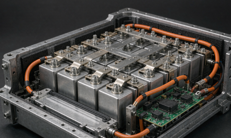
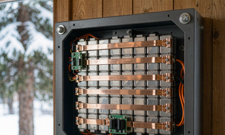
- LiFePO4 (LFP) – my default for rechargeable sensor packs. Cycle life of 3,000 to 6,000 cycles at 80% depth of discharge, outstanding thermal stability, and a flat 3.2V discharge curve that simplifies power management. The trade-off is lower energy density, which matters when the enclosure is small.
- Li-ion NMC – better energy density (useful for compact nodes), but shorter cycle life and tighter thermal constraints. Acceptable when the duty cycle is light and the temperature range is moderate.
- Lithium thionyl chloride (Li-SOCl2) – the workhorse of ultra-long-life primary nodes. Self-discharge below 1% per year and up to 15-20 year service life at low drain rates. Non-rechargeable, so the replacement plan must be designed in from day one.
- Sodium-ion – an emerging option for cold-climate sensor networks; it retains usable capacity well below -20°C where LFP charging becomes restricted below 0°C without a heating strategy.
For a node that sleeps at microamps and wakes to transmit a few times per hour, the average drain may be under 1 mA. At that rate, a primary Li-SOCl2 D-cell with 19 Ah can plausibly run for its full shelf-life limit rather than its capacity limit. For nodes with solar harvesting and daily cycling, LFP wins on total cost of ownership because you replace it once a decade instead of once every two years. Every compliance baseline still applies: cells shipped internationally must pass UN 38.3 transport testing, and rechargeable packs for commercial equipment should be validated against IEC 62133-2.
The Self-Discharge Budget: Where Most Models Go Wrong
Self-discharge is the silent killer of “10-year battery life” claims. Cell datasheets quote self-discharge at 20-25°C, but sensor nodes rarely live at 25°C. Inside a dark polycarbonate enclosure in direct sun, ambient can easily reach 55-60°C, and self-discharge roughly doubles for every 10°C increase. A cell quoted at 1% per year at room temperature can lose 8-10% per year in a hot mounting location – before you account for the BMS quiescent draw.
And that BMS draw is the second item people forget. A protection IC plus a fuel gauge plus a standby radio can easily add 20-50 µA of continuous drain. Fifty microamps is 438 mAh per year – for a small 2 Ah pack, that alone can be more than 20% of capacity annually. I require every sensor battery solution we design to carry a documented self-discharge and quiescent budget with three line items: cell self-discharge at the worst-case site temperature, BMS and electronics standby draw, and connector/leakage allowance. If the sum exceeds 3% of usable capacity per month, the design gets reworked or the maintenance interval gets shortened – deliberately, on paper, not by surprise in year three.
A practical example from a pipeline monitoring project: the original model predicted 5-year life with a 6.6 Ah LFP pack. Field audit showed average node temperature of 38°C, not the assumed 25°C. Corrected self-discharge plus a 30 µA standby draw cut real life to 3.2 years. We caught it in a 40-node pilot instead of a 4,000-node rollout, which is exactly why pilots exist.
Thermal Design and Enclosure Engineering
Reliability is as much mechanical and thermal as it is electrochemical. Three enclosure practices consistently move the needle:
- Thermal mass and shading. Mounting the battery low in the enclosure, isolating it from electronics waste heat, and using light-colored or reflective enclosures can cut peak internal temperature by 10-15°C. That single change can double cell calendar life.
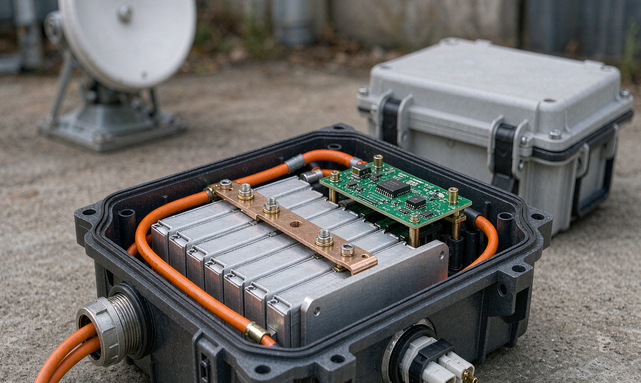
- Condensation control. Breather membranes (Gore-Tex style vents) equalize pressure without admitting liquid water, while conformal-coated PCBs and potting on the connector side prevent the corrosion failures that mimic “battery death.”
- IP ratings matched to the site. IP67 works for buried and washdown environments; IP65 with a breather vent is often more reliable long-term above ground because it avoids the pumping action that degrades gaskets during thermal cycling.
For cold climates, low-temperature charging is the constraint most often missed. Standard LFP should not be charged below 0°C; doing so plates lithium onto the anode and permanently reduces capacity while creating a latent safety risk. Where winter charging is unavoidable, we integrate a heating film controlled by the BMS, or we size the solar array so charging windows naturally occur in the afternoon warm hours. Validation against IEC 60068-2-1 and IEC 60068-2-2 (cold and dry heat) plus thermal shock cycling per IEC 60068-2-14 is part of our standard release process for sensor packs.
BMS Reliability: Protection Without False Lockouts
The BMS should protect the cells without manufacturing its own failures. In sensor applications I look for four characteristics. First, microamp-level sleep current – under 10 µA is achievable with modern AFEs. Second, hysteresis-based under-voltage lockout that releases cleanly after recovery, because a latching protection state in a node with no user nearby equals a dead node until the next site visit. Third, cell balancing that actually works at the low currents sensor packs see; passive balancers specified at 60 mA may never correct imbalance in a pack that spends 99% of its life asleep. Fourth, documented behavior under brownout and recovery, since solar-powered nodes ride through daily voltage swings thousands of times per year.
We also validate the BMS against the abuse conditions of IEC 62619 for industrial applications – overcharge, short circuit, and thermal abuse – because a protection board that fails closed in a remote node is a service call, and one that fails open dangerously is a liability. For fleets, adding a coulomb-counting fuel gauge with an accessible state-of-health register lets the network operations team trend degradation remotely instead of guessing.
Building the 10-Year Replacement Plan
The most reliable fleets plan battery replacement as a scheduled event, not an emergency response. My planning framework has four steps:
- Model the fade curve. Use 80% end-of-life capacity as the planning floor, apply the site-specific temperature acceleration, and derive the year at which the node first violates its minimum autonomy requirement (for example, 14 days of operation with no solar input).
- Pilot before scaling. Instrument 1-2% of the deployment with per-node telemetry for at least two full seasons. Correct the model with real temperature and duty-cycle data – the pipeline project above is the cautionary tale.
- Design for the swap. Connectors rated for the number of mating cycles, modules secured with captive fasteners rather than adhesive, and pack form factors that a technician can replace in under five minutes. Every minute of truck-roll time is the real cost driver.
- Stage replacements by cohort. Replace at 80-90% of modeled life, grouped geographically, so a single maintenance route covers a whole cluster. Running cells to actual failure converts a planned $40 swap into an unplanned $300 site visit.
Done properly, this turns battery replacement from the top failure driver into a predictable line item. One utility-scale environmental monitoring customer of ours moved from reactive replacements (averaging 11% of nodes offline in any given month) to cohort-based swaps and now sustains 99.6% fleet availability with quarterly maintenance routes.
Validation and Field Data: How We Prove Reliability Before Shipment
A reliability claim without data is marketing. Our standard validation sequence for a sensor battery solution includes: capacity verification at three temperatures, cycle life testing at the customer’s actual duty cycle (not a generic 0.5C profile), self-discharge measurement over 28 days with temperature extrapolation, vibration and shock per IEC 60068-2-6 and IEC 60068-2-27, ingress testing to IEC 60529, and a UN 38.3 sequence for transport certification. For medical-adjacent or safety-critical sensing, we add IEC 62133-2 cell-level certification review and, where relevant, UL 1973 for stationary standby use.
Just as important is what happens after deployment. We ask fleet operators to export state-of-health and charge-event telemetry quarterly. Across the last three years of programs, that data has shown a consistent pattern: packs maintained within a 20-80% state-of-charge window and kept below 40°C average temperature degrade at roughly half the rate of packs cycled to full and parked hot. Those two operational levers – charge windows and thermal management – are free, and they routinely add 3-4 years of service life.
Practical Checklist Before You Deploy
- Chemistry matched to duty cycle, temperature range, and service-life target
- Self-discharge + quiescent budget documented at worst-case site temperature
- BMS with microamp sleep, clean UVLO recovery, and functional balancing at low current
- Enclosure with thermal isolation, pressure equalization, and correct IP rating
- Low-temperature charging strategy (heater, chemistry choice, or charge-window scheduling)
- Certification file: UN 38.3, IEC 62133-2 or IEC 62619 as applicable, ingress and environmental test reports
- Pilot instrumented for at least two seasons with telemetry-driven model correction
- Cohort-based replacement schedule with connector/fastener serviceability designed in
Conclusion
Battery solution reliability for sensors is won in the modeling and lost in the details – the forgotten standby current, the underestimated enclosure temperature, the balancer that never gets a chance to work. Treat the battery as the availability-critical subsystem it is, budget its losses explicitly, validate against the real duty cycle, and plan the replacement cadence before the first node ships. Fleets that do this routinely exceed 99.5% uptime over a decade of operation; fleets that do not spend their budget on truck rolls instead. If you are scoping a sensor deployment and want a second pair of engineering eyes on the power budget, the team at Horizon Power reviews duty-cycle data and site conditions as a standard part of every battery solution engagement.
FAQ
How long can a battery-powered sensor node realistically last in the field?
With a primary Li-SOCl2 cell at low duty cycle, 10-15 years is achievable when self-discharge and standby draw are properly budgeted. Rechargeable LFP packs with solar harvesting are typically planned for 8-12 years with one mid-life inspection. The limiting factor is almost always temperature-weighted self-discharge plus BMS quiescent current, not raw cell capacity.
Why does my sensor battery die faster in summer even though usage is constant?
Self-discharge and BMS standby draw both accelerate exponentially with temperature – roughly doubling every 10°C. An enclosure that reaches 55°C in summer sun can see 8-10 times the room-temperature self-discharge rate. Shading, ventilation strategy, and thermal mass inside the enclosure are usually more effective than simply specifying a larger cell.
Can I charge LiFePO4 sensor packs below freezing?
Not without precautions. Charging below 0°C causes lithium plating that permanently reduces capacity and can create safety hazards. Options include a BMS-controlled heating film, choosing a low-temperature-rated cell formulation, or scheduling charge windows into warmer hours. Discharge below freezing is generally fine for LFP, with some capacity reduction.
What certifications should a sensor battery solution have before deployment?
At minimum, UN 38.3 for transport. For commercial and industrial equipment, IEC 62133-2 (portable/sealed cells) or IEC 62619 (industrial stationary and motive) are the usual references, with UL 1973 relevant for stationary standby designs. Environmental validation to IEC 60068 series and ingress rating per IEC 60529 completes the file.
How do I decide when to replace batteries across a large sensor fleet?
Model each cohort’s fade curve using measured site temperature and duty-cycle data from the pilot, then schedule replacement at 80-90% of modeled life, grouped geographically. Trending state-of-health telemetry per node lets you refine the schedule annually. Reactive replacement after failure typically costs 5-10 times more per node than planned cohort swaps due to truck-roll economics.