Battery Solution Testing for Robotics: End-of-Line Functional Screening, Duty-Cycle Emulation, and Field Telemetry Correlation
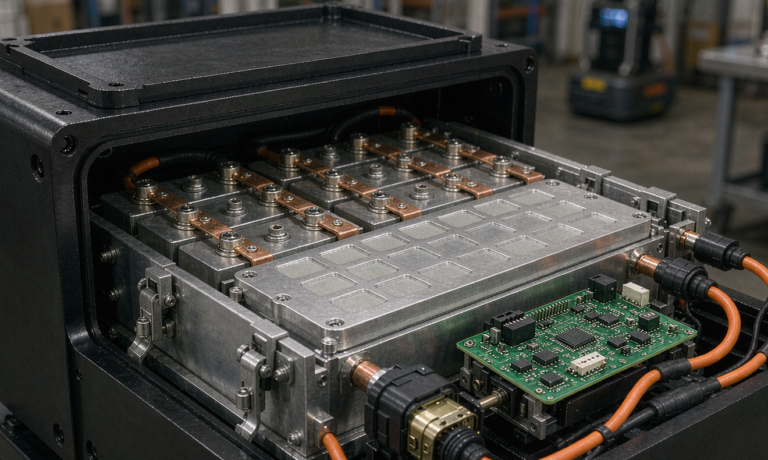
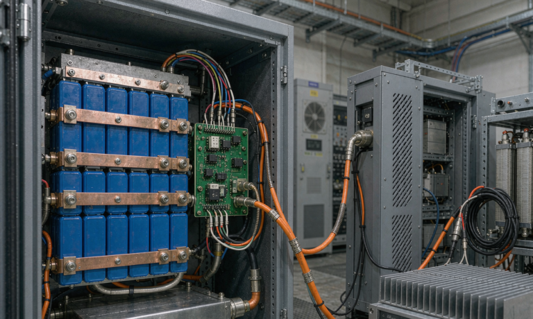
Every robotics programme I have supported eventually arrives at the same uncomfortable moment: the fleet is deployed, the robots are moving, and somebody asks why pack number 217 keeps throwing a low-voltage fault that the other two hundred packs never show. Nine times out of ten, the answer is not a bad cell. It is a gap in the test plan that let a marginal weld, a drifting shunt, or a firmware edge case slip through. I am Karl Huang, a senior lithium battery engineer at Horizon Power, and in this article I will walk through the battery solution test architecture we use for autonomous mobile robots (AMRs), automated guided vehicles (AGVs), and inspection drones — from incoming cell screening to end-of-line functional checks, duty-cycle emulation on the bench, and the correlation work that ties field telemetry back to design limits.
Why Robotics Battery Testing Is Its Own Discipline
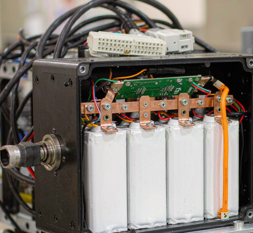
Robotics packs are frequently treated as small EV packs, and that framing causes most of the early test-plan mistakes. An electric-vehicle pack is energy-limited and thermally managed by a large liquid loop; a robotics pack is power-limited, air-cooled or passively cooled, cycled two to six times per day at partial states of charge, and physically abused by vibration, torsion, and washdown. The duty profile of a warehouse AMR — 18 hours of running, repeated opportunity charges at 20 to 80 percent state of charge, and cold overnight dwell in an unheated dock — stresses different failure mechanisms than either an EV or a drone battery, which lives at high C-rates but shallow daily depth of discharge.
That is why we treat a custom battery solution for robotics as a dedicated test discipline with three layers: incoming and in-process verification (are the parts what the certificate says they are), end-of-line functional screening (does this specific pack behave like its datasheet), and type validation against the relevant standards (does the design survive the abuse the standard anticipates). The three layers answer different questions, and none of them can substitute for the others.
The Standards Framework: What Each Standard Actually Covers
Robotics packs usually sit under a stack of overlapping standards, and procurement teams frequently ask for the wrong one. Here is how I map them:
- UN 38.3 — transport qualification. Altitude, thermal, vibration, shock, external short, impact/crush, overcharge, and forced discharge. Mandatory for shipping the pack by air, sea, or road; it says nothing about long-term cycle life.
- IEC 62133-2 — safety requirements for portable sealed lithium cells and batteries. Commonly cited for smaller service robots and consumer-adjacent products; covers external short, overcharge, thermal abuse, and mechanical shock at cell and small-pack level.
- IEC 62619 — safety for industrial-use lithium cells and batteries. This is the anchor standard for most AMR and AGV packs above the portable threshold, including propagation resistance and design evaluation.
- UL 2271 — batteries for use in light electric vehicles and, in practice, frequently referenced for mobile robots in North American deployments; it emphasizes field-failure modes and manufacturing consistency.
- IEC 60068-2-6 / -2-27 / -2-14 — sinusoidal vibration, shock, and thermal shock methods. Robotics integrators usually specify these with application-specific severity levels rather than the default transport severities.
- EN 61000-6-2 / EN 61000-6-4 — industrial EMC immunity and emission. Robotics packs share chassis space with motor drives and LiDAR; BMS firmware must tolerate the conducted and radiated environment.
- ISO 13849-1 / IEC 61508 — functional safety of the wider robot control system. When the battery disconnect is part of the safety function (emergency stop loops, safe torque off), the BMS contactor logic inherits a performance level requirement.
The practical point: UN 38.3 gets your pack on a truck, IEC 62619 keeps the certification body and the insurance underwriter comfortable, and the 60068 and EMC series keep the pack alive in the actual robot. A test plan that only quotes UN 38.3 is a shipping document, not an engineering validation.
Incoming Cell and Sub-Assembly Verification
The cheapest place to catch a defect is before it is welded into a stack. For every incoming cell lot we sample four things: capacity at 0.2C against the lot certificate, DC internal resistance (DCIR) at 50 percent state of charge using a four-wire Kelvin measurement, open-circuit voltage consistency after a 72-hour rest (a proxy for self-discharge uniformity), and visual inspection of terminal flatness. On a recent 21700 lot intended for a high-rate AGV pack, the DCIR distribution ran 14.2 to 26.8 milliohms across 5,000 cells — a 1.9x spread that would have produced a badly imbalanced parallel group if we had skipped binning. We bin into three DCIR grades and assemble packs from a single grade.
Sub-assembly verification is where robotics packs differ most from consumer packs. Weld joints get pull-tested on a per-shift coupon: for nickel-plated steel busbars on cylindrical cells we expect peel failure in the nickel coating, not clean separation at the weld nugget, and a nugget-diameter below 2.2 millimetres on a 0.2-millimetre-thick strip is an automatic process stop. BMS boards go through a bed-of-nails functional fixture that exercises every protection path — over-voltage, under-voltage, over-current, over-temperature on both thermistor channels, and the charge/discharge FET gate drive — before the board is allowed onto a stack.
End-of-Line Functional Screening: What Every Pack Must Pass
End-of-line (EOL) testing is the layer customers see on the acceptance report, and it is where consistency is won or lost. Our standard robotics EOL sequence runs eight checks on 100 percent of packs:
- Capacity verification at the pack rating current, typically 0.5C for robotics, within ±4 percent of nameplate.
- DCIR at two states of charge (90 percent and 25 percent), trended against a statistical process control chart with a 3-sigma gate.
- Self-discharge screen: 24-hour open-circuit stand with a voltage-drop limit that correlates to less than 2 percent capacity loss per month.
- Full protection trip validation: charge over-voltage, discharge under-voltage, discharge over-current, short-circuit, and both temperature limits, with trip points recorded against the BMS datasheet tolerance.
- Cell-group imbalance audit: maximum spread across series groups at rest and under a 1C pulse.
- Insulation resistance at 500 VDC, pack-to-chassis, with a 20 megohm minimum for 48 V systems.
- Communications handshake over CAN 2.0B or RS-485 as fitted, including SoC reporting plausibility and fault-code injection.
- Vibration cosmetic-and-torque check on a sampled basis: fastener torque audit at marked points plus a low-level 10–55 Hz sweep to catch loose harnesses.
The two EOL checks most often skipped by low-cost suppliers are the short-circuit trip and the communications fault injection, because both require fixtures and firmware hooks that take real engineering time to build. They are also the two checks whose absence produces the classic field failures: a pack that does not clear a hard short through its main contactor, and a pack whose SoC reading freezes after a bus fault and strands the robot mid-aisle.
Duty-Cycle Emulation on the Bench
Passing a static discharge test tells you very little about a fleet’s future. The bench layer that actually predicts field behaviour is duty-cycle emulation: recording the current, temperature, and state-of-charge profile from a reference fleet or from the robot OEM’s simulation, then replaying that profile through a programmable regenerative DC source on the pack. Regeneration matters. An AMR decelerating from 1.5 metres per second with a 250 kilogram payload pumps a 60–120 ampere charge pulse back into the pack for one to two seconds, several hundred times per shift, and charge acceptance at high state of charge is where many BMS firmwares trip unexpectedly.
Our standard robotics emulation profile interleaves three segments: a discharge block following the route histogram (peak-to-average ratio typically 2.8:1 for parcel-sortation AMRs), a regen block placed at 70–90 percent SoC where charge over-voltage trips cluster, and a dwell block at the dock with the charger’s actual taper profile. We run the profile at 25 °C and at 0 °C, because cold regen is the single most common trigger for nuisance over-voltage faults — cell impedance roughly doubles from 25 °C to 0 °C, the charge pulse lands on a stiffer cell, and a BMS with a fixed over-voltage threshold and no temperature compensation will trip. The design fix is usually a temperature-derated charge-current table in the BMS, but you will never discover the need for it without replaying the duty cycle cold.
For a recent 48 V 40 Ah AGV programme, the emulation campaign exposed a fault that static testing had passed cleanly: at 0 °C and 85 percent SoC, the first 90-ampere regen pulse hit 4.28 volts per cell group and tripped charge FETs for 30 seconds, three times per shift. The fix — a derating table pulling charge current to 40 amperes below 5 °C — cost a firmware release. The field alternative would have been a fleet of robots losing charging time in winter.
Environmental and Abuse Validation Beyond the Datasheet
Type testing against IEC 62619 and UN 38.3 sets the floor. Robotics integrators should add severity on the axes their application actually stresses. For vibration, a floor-standing AGV on a hard warehouse slab sees a milder spectrum than an AMR crossing dock plates; we typically specify IEC 60068-2-6 sweeping 10–150 Hz at 1 g for 20 cycles per axis for warehouse units, and 3 g with random-profile additions for field robots and agricultural units. For thermal shock, IEC 60068-2-14 with −20 °C to +60 °C transitions, 50 cycles, is a reasonable robotics screen because the failure it targets — solder-joint fatigue on the BMS power stage and busbar lugs — is cumulative and invisible at delivery.
Abuse validation deserves one non-negotiable: a single-cell thermal runaway propagation test, whether done to IEC 62619 clause 7.3.3 or to a customer-specified method, on the exact pack geometry being shipped, including the venting path through the enclosure. On a robotics pack the enclosure is usually sheet metal with a gasketed lid, and the question is not whether the cell can be driven to failure but whether the hot gas exits through the designed vent port instead of lifting the lid and involving the neighbouring cells. We verify this with a heater-induced runaway on the engineering build, temperature instrumentation on every third cell, and a post-test teardown that documents which protection held.
Correlating Bench Data with Field Telemetry
The final layer is the loop most programmes never close: connecting bench measurements to what the fleet reports. Every Horizon Power robotics pack logs per-cycle ampere-hour throughput, min/max cell temperatures, voltage-sag events, and protection trips to non-volatile memory, and uploads them through the robot’s CAN-to-cloud link. The correlation work is simple in concept and unforgiving in execution: for each field fault class, find the bench metric that predicts it, then set an EOL or incoming gate on that metric.
Three examples from our own fleet data. First, packs that later threw chronic under-voltage faults had shown EOL DCIR values one to two milliohms above the pack-family mean — individually within tolerance, statistically a red flag — so we tightened the gate from 3-sigma to a hard 2.2-sigma limit. Second, weld-resistance scatter measured on EOL milliohm-mapping of parallel groups predicted capacity divergence at 800 cycles with an r² of 0.81 in our data, which moved weld QC from coupon-only sampling to a 100 percent four-wire resistance scan on busbars for high-rate programmes. Third, packs that logged repeated cold-regen trips almost always shipped from lots whose BMS firmware predated the temperature-derating table — so firmware version became a tracked lot attribute, and a mismatch between build sheet and flashed firmware is now an automatic EOL hold.
The practical output of this loop is a living test plan. The plan you ship with pack revision A should not be the plan you ship with revision C, because the fleet has already told you which of your assumptions were wrong.
Building the Test Plan: A Practical Sequence
For integrators procuring a robotics battery, I recommend requiring the following evidence sequence from any supplier, in this order: incoming cell lot certificates with sampling data (not just certificate copies); DCIR binning records for the specific build lot; a complete EOL report per shipment with the eight checks above; type-test reports for UN 38.3 and IEC 62619 on the exact enclosure geometry; application-severity vibration and thermal-shock reports referencing IEC 60068-2-6/-27/-14 with the severity levels stated; an EMC report against EN 61000-6-2/-4; and a duty-cycle emulation report describing the replay profile, temperatures, and any BMS firmware changes it triggered. A supplier who produces all seven without prompting has almost certainly shipped robotics packs before. A supplier who hesitates on the duty-cycle emulation report is telling you that their validation stopped at the standards minimum — which is exactly where the fleet’s mystery faults are born.
Frequently Asked Questions
What is the difference between battery solution testing and standard cell testing?
Cell testing characterizes an electrochemical component; battery solution testing validates a finished system including BMS logic, thermal design, enclosure, connectors, and firmware under the application’s real duty cycle. A pack can be built entirely from excellent cells and still fail in the field because the BMS charge-derating table, a weld process, or an EMC immunity gap was never exercised.
Which standards apply to an AMR or AGV lithium battery pack?
At minimum UN 38.3 for transport and IEC 62619 for industrial battery safety. Most robotics deployments additionally need IEC 60068-2-6/-27/-14 at application severity, EN 61000-6-2/-4 EMC immunity and emissions, and — in North America — UL 2271 or UL 1973 depending on the configuration. If the battery disconnect participates in the robot’s safety function, the relevant clause of ISO 13849-1 applies to that path.
How long does a full robotics battery validation take?
For a typical 24–48 V LFP robotics pack, expect 3 to 4 weeks for EOL fixture bring-up and duty-cycle emulation on an existing platform, plus 6 to 10 weeks for type testing (UN 38.3 and IEC 62619) at an accredited lab. First-time platforms with a new enclosure geometry should budget on the longer end of both, because propagation and vibration tests almost always surface one enclosure iteration.
Why do cold regen pulses trip the BMS in winter?
Cell internal resistance roughly doubles from 25 °C to 0 °C, so a regenerative braking pulse that is harmless in summer lands on a much stiffer cell and pushes group voltage past the charge over-voltage threshold. The fix is a temperature-derated charge-current table in the BMS firmware — and the only reliable way to find the threshold values is cold-duty-cycle emulation before the fleet ships.
What end-of-line tests should I insist on when auditing a battery supplier?
Require 100 percent coverage of short-circuit trip validation, over/under-voltage and over-current trips, both thermistor channels, insulation resistance at 500 VDC, DCIR trended on an SPC chart, and CAN/RS-485 fault-code injection. Suppliers routinely skip the short-circuit trip and the communications fault injection because they need custom fixtures — their absence is the strongest single signal that a supplier’s testing is superficial.
Can field telemetry really predict pack failures before they happen?
For certain failure modes, yes. In our fleet data, EOL DCIR scatter predicted later under-voltage faults, weld-resistance scatter predicted capacity divergence at 800 cycles (r² of 0.81), and firmware-versus-build-sheet mismatch predicted chronic cold-regen trips. Not every failure is predictable — connector corrosion and impact damage are not — but the statistically predictable fraction is large enough that closing the telemetry loop is the highest-leverage improvement most robotics battery programmes can make.