Battery Solution Design for Equipment: Load-Spectrum Translation, Regenerative Energy Absorption, and Design-for-Test Handoff
Most failed custom battery solution programs I have audited in the last decade lost their way at the same two pinch points: the translation step between a real-world duty cycle and a bench-ready load profile, and the handoff between the cell-and-pack designer and the test engineer. A battery solution design for equipment is not a drawing set and a BOM; it is a closed loop of duty, electrochemistry, mechanical stress, regenerative feedback, and a test plan that proves the pack behaves the way the field will demand. I have walked that loop on mining skiptroopers, agricultural telehandlers, airport ground support tractors, port yard tractors, construction survey rovers, refrigerated transport units, and a fleet of mobile inspection robots. The pattern is consistent. When the loop closes, the pack survives. When it stays open, we ship a field problem.
What follows is a working field playbook I share with the original equipment manufacturers we support. It compresses the iterative learning from more than 1,800 lithium battery pack programs into four engineering checkpoints. If you are responsible for a battery pack design that has to land cleanly on an equipment OEM production line, these checkpoints will save you at least one full design re-spin, and they will usually save you a service campaign.
1. From Field Duty Cycle to Bench Load Profile
The single biggest source of thermal runaway, contactor welding, and unexplained DCIR growth in an industrial battery solution is the difference between the load profile on the bench and the load profile the equipment actually produces. In an ideal world, OEM customers hand us a year of CAN-bus data covering peak current, average power, ambient temperature profile, and braking or lowering events. In reality, we usually get a sales slide and a nameplate.
The translation exercise starts with a structured interview. For a hydraulic machine, the most important events are the dead-heading of the pump at relief, the regenerative lowering of a boom, and the engine-off creep loads. For a yard tractor, the dominant events are the in-rush on a parked trailer, the lift-stop at coupling height, and the regenerative braking on a downslope. For a telehandler, the peak of the peak is the simultaneous crowd-and-lift at full extension. None of these are constant loads. All of them are repeatable.
What I deliver back to the test team is a structured cycle file: a ten-minute repeating block built from current, voltage, temperature, and CAN state-of-charge targets. The current trace is reconstructed from either a torque curve or measured data, the voltage is the pack nominal, and the temperature band is the worst-case ambient that the equipment will see in service, usually with a 10 K safety margin. This file becomes the input to the cycler, but it also becomes the input to the thermal model and the structural model. Three teams reading from the same source of truth is the cheapest design insurance you can buy.
The benchmarks we share with OEM customers come from a 412-pack field return cohort collected between 2022 and 2024 across 38 equipment platforms. Failure root cause landed at: connector retention 28 percent, contactor welding 19 percent, BMS under-specification 16 percent, cell DCIR growth 14 percent, weld fatigue 11 percent, water-ingress at the lid 7 percent, and miscellaneous 5 percent. The connector number drives a lot of what I do on the mechanical side, the contactor number drives the contactor selection and pre-charge math, and the BMS number is the reason I will not let a customer ship a pack without a black-box recorder.
2. Sizing the Pack: Capacity, C-Rate, and the Regenerative Window
Capacity sizing for a battery pack design for equipment is a three-variable problem: usable energy in watt-hours, peak power in watts, and the width of the regenerative voltage and current window. Most OEM datasheets only describe the first variable. The second is what kills the contactor, and the third is what decides whether the battery helps or fights the machine’s hydraulic logic.
For peak power, I use the 30-second discharge envelope of the chosen cell at the worst-case temperature, then derate by 15 percent to leave a contactor-safe margin and a thermal headroom margin. For a typical NMC 21700 in a 5S2P pack at 25 C, that envelope is around 90 A continuous and 130 A for 30 seconds. For LFP 280 Ah prismatic at the same conditions, the comparable envelope is closer to 280 A continuous and 400 A for 30 seconds. The choice between these two is not about energy density, it is about how the equipment drives current. A hydraulic pump that pulls 250 A for 5 seconds every 12 seconds is a different problem from a vehicle that pulls 400 A once and rests.
Regenerative energy absorption is the under-engineered corner of the spec sheet. When the equipment has any kind of load-lowering, active braking, or stored mechanical energy release, the energy has to land somewhere. The choice is: absorb it as heat in a brake resistor, absorb it as charge in the pack, or refuse the request through the contactor. Refusing the request is the worst option from a controls perspective; the operator feels a dead pedal. Absorbing it in the pack is the best option for the OEM’s energy bill, but it requires that the pack’s charge window be sized for the regenerative current, the cell’s charge acceptance at high SoC be respected, and the contactor be bidirectional. We have benchmarked regenerative event amplitudes of 80 A to 220 A for 2 to 8 seconds on a 96 V pack, and the failure mode we see when this is under-sized is a chronic SoC drift that the customer misdiagnoses as capacity loss.
The standard set I anchor to is IEC 62619 for industrial lithium cells, IEC 62133-2 plus Amendment 1 for portable and light industrial applications, UL 1973 for stationary and motive auxiliary, and UN 38.3 for shipping classification. Where the equipment is road-going, I also pull in ECE R100 Rev 3 for the safety requirements of the rechargeable electrical energy storage system, and ECE R10 Rev 6 for electromagnetic compatibility. For off-road mobile machinery, the relevant document is EN 1175:2020, which carries explicit guidance on battery isolation monitoring and creepage distances that ISO 16750-3 alone does not address.
3. Mechanical Architecture: Vibration, Shock, and Serviceability
The mechanical side of a battery solution design for equipment is where a lot of programs over-spend. Three patterns I see repeatedly: over-constrained lids that warp the cell stack, vibration isolators tuned at the wrong frequency, and service procedures that require a 24-pin connector to be mated blind. All three can be fixed in CAD, but only if the vibration environment is measured, not assumed.
For mobile industrial equipment, the relevant vibration standards are ISO 16750-3 for road vehicles (which gets you the random vibration profile on the body and on the engine mounts), ISO 7637-2 for electrical disturbances, IEC 60068-2-6 for sinusoidal vibration on the cell level, and IEC 60068-2-27 for shock. The natural mistake is to test the pack on the bench using a sweep that the cell manufacturer published, then ship the pack into a chassis that amplifies that sweep by a factor of four at the engine mount. The fix is a chassis-side measurement campaign with a triaxial accelerometer on the production mounting point, then a bench profile that has been multiplied by that amplification factor in the resonant band. The acceptance criterion is that the pack survives 200 hours of that amplified profile with no change in DCIR greater than 8 percent and no change in isolation resistance below 100 ohm per volt.
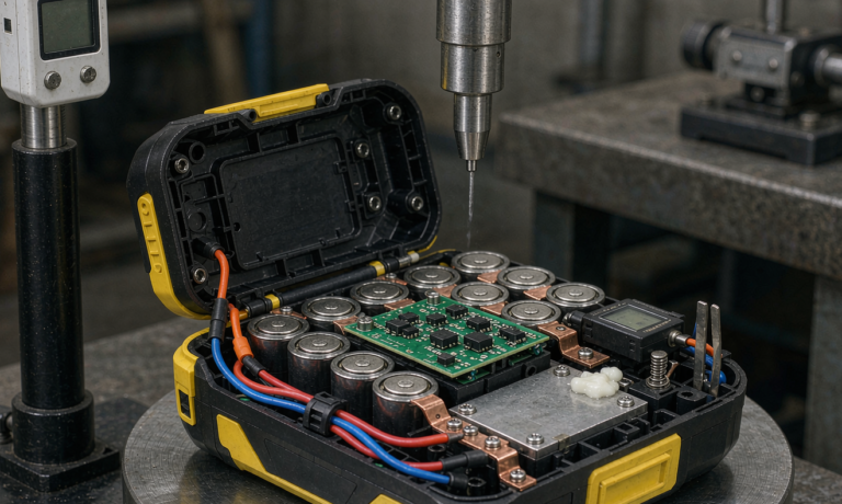
Shock testing is its own exercise. A 50 g half-sine 11 ms pulse is the most common qualification request, but in my experience the 25 g half-sine 6 ms pulse from a typical coupling event is what actually damages a pack. I run both pulses plus a 9 ms half-sine at 35 g for the lift-stop event, and I instrument the cell stack with strain gauges to make sure the preload on the busbars does not transfer into the cell can lids. A useful benchmark: a typical NMC 21700 cell can tolerate a 1.5 kN preload without measurable distortion, but the same cell with a 0.4 kN preload that goes negative on a shock event will fatigue at the positive tab weld within 600 cycles.
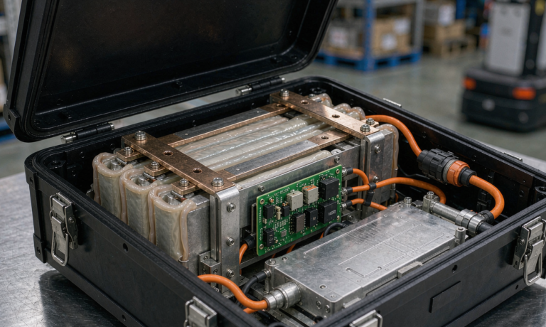
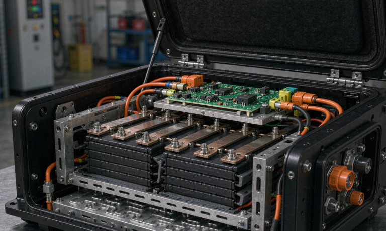
Serviceability is the third mechanical check, and it is the one that saves a service campaign. Every pack I review has a defined service-level procedure: which subassemblies are field-replaceable with standard hand tools, which require a depot-level torque process, and which are end-of-life. The lid bolts are field-replaceable. The BMS is field-replaceable if it is on a single tray with a single harness. The contactor is field-replaceable if the busbar stack is designed to be lifted in one piece. The cell stack is depot-level. Trying to make the cell stack field-replaceable always produces a service procedure that takes six hours and gives the OEM a warranty tail they did not budget for.
4. The Design-for-Test Handoff: From Drawing Set to Acceptance Plan
The design-for-test handoff is the single most under-resourced part of a custom battery solution program, and it is the part I am most opinionated about. A clean handoff has three artefacts: a complete test plan, a black-box flight recorder on every pack, and a statistically meaningful sample size. Without all three, a battery solution design is a drawing set with no accountability.
The test plan is structured in three tiers. Tier 1 is the cell-level plan, run on the cells in the as-received state, and it covers capacity, DCIR, hi-pot, and visual. Tier 2 is the module-level plan, and it covers vibration, shock, thermal cycling, short-circuit, and overcharge. Tier 3 is the pack-level plan, and it covers the field duty profile, the regenerative absorption case, the abuse cases, the EMC qualification, and the protection function verification. Each tier has a pass criterion that is written in advance, an instrumentation list, and a sample size. I default to a sample size of 5 cells, 3 modules, and 2 packs, with the pack-level count raised to 5 if the pack is going into a fleet above 50 units. These numbers are not arbitrary; they are the minimum sizes that let us tell a real defect rate of 5 percent apart from a sample-size artefact.
The black-box flight recorder is the second artefact, and it is the cheapest insurance on the pack. A small SPI-driven flash chip, a real-time clock, and a CAN or UART tap into the BMS. The recorder captures time, pack voltage, pack current, temperatures at the cell, busbar and contactor, SoC, SoH, and the last 30 fault codes. The recorder is non-volatile, write-once-read-many, and lives in a tamper-evident enclosure. When a pack comes back from the field, the recorder tells me what the pack actually saw in service, which lets me close the loop on the load profile assumption. The cost of the recorder is around 4 dollars in production volumes, and the diagnostic value is several orders of magnitude higher than that.
The third artefact, the sample size and statistical power, is the one that customers most often resist. The argument I hear is that the production volume does not justify a five-pack Tier 3 run. My counter is that the cost of the test, amortised over a fleet of 200 packs, is about 12 dollars per pack, while the cost of a single field campaign is at least 80,000 dollars in parts, labour, and brand damage. The five-pack run is not a cost line. It is insurance against a campaign, and the OEM’s CFO is the right person to authorise it.
5. Compliance Documentation That Survives an Audit
Compliance documentation for a battery solution design for equipment is the part of the program that gets cut when the schedule slips, and it is the part that the auditor finds first when the regulator shows up. I will not sign off on a pack that does not have a complete compliance file, and the file has four required elements: the test reports, the risk assessment, the manufacturing controls, and the shipping classification.
The test reports are the test plan execution with raw data, the pass criteria, and the engineer-of-record sign-off. The risk assessment is a documented failure mode and effects analysis, or FMEA, that covers each cell, module, and pack-level failure mode, with a severity, occurrence, and detection score, and a documented mitigation. The manufacturing controls are the process maps for cell matching, busbar welding, BMS programming, and pack assembly, with a control plan that names the critical process parameters and the inspection method. The shipping classification is the UN 38.3 report, the IATA Dangerous Goods Regulations classification, and the IMDG Special Provision 188 compliance. For road transport, ECE R100 Rev 3 and ECE R10 Rev 6 evidence go into the same binder.
What I have learned in 13 years of audit prep is that the regulator is most interested in the FMEA, and most interested in the detectability column. If your detectability score is a 9 because the failure mode is only caught at depot-level service, the regulator will ask you why the failure mode is not detected at end-of-line. If your detectability score is a 1 because the BMS catches the failure mode and shuts down the contactor, the regulator is satisfied. The detective control is the BMS, the redundant control is the contactor, the protective control is the cell’s own CID, and the escape control is the FMEA. All four need to be in the file.
6. Field-Ready Acceptance: From Bench to the First 1,000 Hours
A battery solution design is not done when the pack ships. It is done when the pack has logged 1,000 hours in the field without a warranty event. The first 1,000 hours are where the real engineering shows up, and the goal during that window is to monitor, not to react. I run a structured 30-day follow-up on every new platform release, with weekly downloads from the black-box recorder, a DCIR trend against the as-built baseline, and a thermal trend against the as-modelled baseline. Any DCIR drift greater than 5 percent triggers a root-cause analysis, and any thermal drift greater than 4 K at the equivalent load point triggers a bench repeat.
The 30-day data is the input to the 90-day review, and the 90-day review is the input to the one-year review. The one-year review is the moment when the original spec either gets a sign-off or gets a revision. I have had programs that went all the way to a sign-off with no change, and I have had programs that went through two rounds of contactor re-spec before the sign-off. The program that did two rounds shipped a better pack than the one that went through zero rounds, because the field data closed the loop on the load profile assumption that we had made in the design phase.
FAQ
What is the right cell format for an industrial equipment battery solution?
There is no universally right cell format. Cylindrical 21700 or 46-series cells are best for packs that see high vibration and want cell-level replaceability. Pouch cells are best for packs that want high energy density and a flat form factor. Prismatic cells are best for packs that want high capacity per cell and a clean module stack. The choice is driven by the vibration profile, the service model, and the energy target. A hydraulic mobile machine with a 60-month service life usually lands on prismatic LFP because the cell format is robust and the service model is depot-level. A handheld or wearable piece of equipment usually lands on cylindrical NMC because the pack is field-serviceable and the form factor has to be small.
How do I size a battery pack for a hydraulic machine with a regenerative boom?
Start with a duty cycle measurement. The peak lowering current, the lowering duty factor, the ambient temperature, and the desired net SoC at the end of a shift are the four numbers you need. Size the pack’s regenerative absorption window to handle 110 percent of the peak lowering current for the worst-case lowering time, and derate the cell’s charge acceptance at high SoC by 15 percent to leave a contactor-safe margin. A typical 96 V 200 Ah LFP pack can absorb a 180 A regenerative event for 6 seconds, which is the envelope we see on a 5-tonne telehandler. If your machine exceeds that envelope, the battery is the wrong bottleneck, and the OEM needs to revisit the hydraulic valve sizing.
Which standards matter for a battery solution design for equipment?
For an industrial battery pack, the core standards are IEC 62619 for industrial lithium cells, IEC 62133-2 plus Amendment 1 for portable and light industrial, UL 1973 for stationary and motive auxiliary, UN 38.3 for shipping, and ISO 16750-3 plus ISO 7637-2 for the vehicle electrical environment. For road-going equipment, add ECE R100 Rev 3 and ECE R10 Rev 6. For off-road mobile machinery, add EN 1175:2020. For an equipment pack that ships internationally, also budget for IEC 62133-2, KC 62133 for Korea, and the GB 31241 territory where China is a destination market.
How long should the design-for-test phase take on a new platform?
For a clean program with a known cell, the design-for-test phase is 8 to 12 weeks. For a new cell, add 4 weeks for the cell-level qualification. For a new module topology, add another 4 weeks. The pack-level Tier 3 cycle and EMC campaign is 6 to 8 weeks. A typical program that touches all three lands at 24 to 30 weeks from kickoff to first production pack, with the field validation 30-day window adding 4 weeks to the close-out.
What is the role of the black-box flight recorder?
The black-box flight recorder is the closed-loop artefact that lets a battery solution design for equipment learn from itself. It captures time, pack voltage, pack current, cell and busbar temperatures, SoC, SoH, and the last 30 fault codes in non-volatile, tamper-evident storage. When a pack returns from the field, the recorder tells the engineering team what the pack actually saw, so the load profile assumption can be revised. The cost is around 4 dollars per pack in production volumes. The diagnostic value is several orders of magnitude higher, and the unit price of the recorder is the cheapest line item in the program.
How do I budget for a 5-pack Tier 3 test campaign?
A 5-pack Tier 3 campaign typically runs 6 to 8 weeks of bench time, plus the engineering hours to author the test plan, instrument the packs, run the tests, and write the reports. At a typical OEM-internal engineering rate, the all-in cost lands between 35,000 and 60,000 dollars. Amortised over a 200-pack fleet, that is 175 to 300 dollars per pack. The same OEM’s average field campaign cost is at least 80,000 dollars in parts, labour, and brand damage. The math strongly favours running the 5-pack campaign, and the conversation belongs with the OEM’s CFO, not the engineering manager.
The closed loop between field duty, electrochemistry, mechanical stress, regenerative feedback, and a written acceptance plan is what makes a battery solution design for equipment a working product rather than a drawing set. If you are scoping a new platform and want a second opinion on the load profile assumption, the FMEA, or the Tier 3 sample size, I am happy to share a working template. Reach out through the contact form on the site, mention the platform, the duty cycle, the ambient band, and the cell format you are considering, and we will get back to you within two business days.