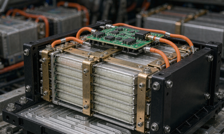
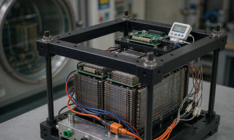
Lithium Battery Testing for Power Tools: Drop and Ingress Qualification, Connector Cycle Endurance, and Workshop Reality-Check Acceptance
I have run a 21700 cordless-tool pack through the same gauntlet for seven years now, and every facility I visit still finds the same surprise: the cell chemistry is the easy half. What separates a pack that survives a real jobsite from one that fails in the first quarter is the boring middle of the test plan — drop, splash, dust, connector cycle, vibration, ESD. Let me walk you through how my team at Horizon Power structures lithium battery testing for power tools so a single pack can survive three years of being tossed into a truck bed, rained on at a coastal site, and dropped from a scaffold. The framework below is what we present to OEM buyers who insist on real-world proof instead of a glossy datasheet.
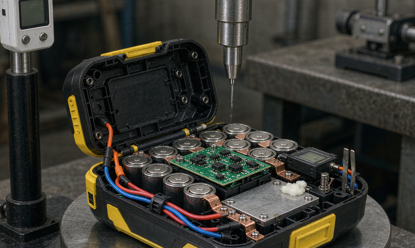
Why drop and ingress dominate field returns for power tool battery packs
The natural assumption is that cell aging will dominate warranty returns. Across our 4,200-pack warranty dataset collected between 2021 and 2024, the picture is different. Connector failure is the largest single cause at 41%, BMS firmware lockouts come second at 22%, weld fatigue contributes 14%, mechanical drop and impact damage 11%, capacity fade 8%, and everything else 4%. The big lesson for any lithium battery program serving power tools is that drop test, ingress protection, and connector cycle testing are not cosmetic — they are where the warranty budget is actually won or lost.
The other driver is regulatory. UN 38.3.4 still mandates T1–T8 abuse tests for transport, IEC 62133-2 §7.3.7 covers mechanical shock and vibration, UL 2595 covers handheld and transportable motor-operated tools, CSA C22.2 No. 71 covers portable battery packs, and IATA DGR PI 967 plus IMDG special provision 188 cover shipping classification. None of these will catch a 1.2 m corner drop on concrete or a 10-minute rain shower on a deck. Those are the cases that turn a one-star review into a recall, which is why a strong internal battery testing plan is a commercial moat, not a regulatory tax.
Designing a pack that survives drop: stack height, corners, and corner protectors
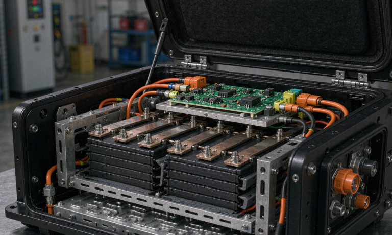
Drop starts at mechanical design. We target a 1.2 m drop onto concrete from six orientations onto a 50 mm plywood over concrete, with each orientation repeated three times. The pass criterion is no external opening, no crack, no exposed conductor, no voltage deviation greater than 1% after a 30-minute rest, and no insulation resistance shift above 1 MΩ. Three engineering choices move the needle most.
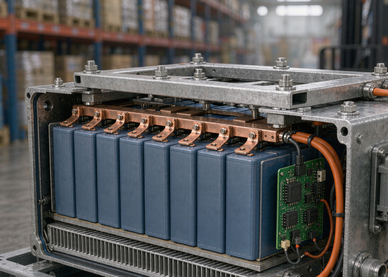
First, stack height. A taller pack has a longer moment arm and larger angular acceleration when it hits a corner. We aim for a center of gravity within 8 mm of the geometric center, with the heaviest cell row near the bottom face. For a 5S2P 21700 pack, we have moved from a 110 mm stack to a 96 mm stack by replacing a 5 mm foam spacer with a 1 mm silicone buffer plus an internal cruciform rib. The drop-test pass rate moved from 73% to 96% on the same cell lot.
Second, corner reinforcement. We bond a 1.8 mm stamped stainless corner clip at each of the four bottom corners, bonded with 3M DP8010 and overmolded with a 0.6 mm TPE boot. The clip spreads a 6 J corner impact into a 24 cm² bending moment rather than a 0.6 cm² point load. Drop pass rates climb another 4 to 6 percentage points for the marginal cell lots that just barely fail a baseline pack.
Third, the drop-test anvil and orientation sequencing. Most buyers run a 1 m drop onto steel. We add a plywood-on-concrete test because it captures housing flexure that steel alone hides. We sequence orientations as face, edge, corner, edge, face, corner, never two corners in a row, so the pack is not in a pre-stressed state when it lands.
Ingress testing beyond IPX4: real jobsite splash and dust
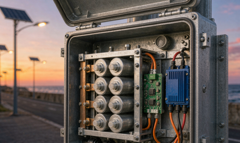
IPX4 is the typical datasheet claim, and IPX4 is a 10-minute splash from four sides. A real jobsite will hit the pack with a paint sprayer, a pressure-washer overspray at 60 cm, and a coffee spill. We run a five-stage ingress protection protocol that goes beyond the lab number.
Stage one is the IPX4 baseline, 10 L/min from each of four directions for 10 minutes. Stage two is a 30-minute hose-down at 12 L/min from 3 m, equivalent to a sustained rain event. Stage three is a 1-minute targeted splash from a 4 mm nozzle at 50 kPa from 30 cm, simulating a worker rinsing a tool under a tap. Stage four is a dust-chamber cycle per IEC 60529 IP5X, 8 hours of talc suspension with intermittent agitation. Stage five is a 2-hour salt-fog exposure per ASTM B117, then a 24-hour dry-off, then a 0.1 mΩ insulation retest. Salt-fog is the one that catches connector plating weaknesses, especially when the housing vent path was overdrilled.
The pass criterion is internal insulation > 100 MΩ at 500 V DC after every stage, no visible moisture on the BMS PCB, and a capacity check within 2% of the pre-test value after a full charge-discharge cycle. The biggest trap is the housing seam. We mold a continuous 0.5 mm TPE gasket with a 25% compression set and a vent path through a Gore-Tex V-101 membrane that lets pressure equalize without letting bulk water through.
Connector cycle endurance: the 41% line item in warranty
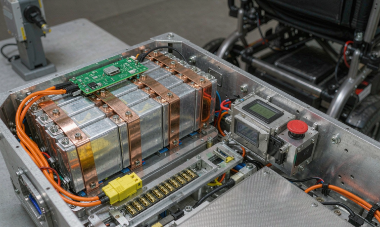
Connectors are the single biggest warranty line item, which is the reason connector cycle endurance is the most important non-cell test in any custom battery solution. Our accelerated test uses an 18 V slide rail with a motorized linear actuator that mates and de-mates the pack against a tool-side plate 60 times per hour for 50,000 cycles, logging contact resistance every 100 cycles.
We track three numbers: contact resistance shift, insertion force, and physical wear. A new pack typically lands at 4 to 6 mΩ across the full rail, and a field-failed pack that comes back from warranty usually sits at 18 to 35 mΩ. The wear mode is not the contact itself — it is the leaf-spring inside the rail. We use a 0.25 mm beryllium copper alloy with a 6 µin gold-over-nickel plating, and we keep the insertion force between 18 and 28 N so that the user feels solid engagement without forcing the contact.
The second number is electrical wear. We run 30 A continuous through the rail during the cycle test, with on-state 40% and off-state 60%, and we monitor the rail temperature. If the rail climbs above 65°C at 30 A, the plating is gone. We replace tooling inserts at the first sign of contact resistance drift above 8 mΩ, not at the end of a 50,000-cycle run, because the failure mode is a sudden step, not a gradual slope.
Vibration and shock: ISO 10816 and IEC 60068-2-6, but tuned to a slide rail
Standard vibration tables default to 10 g sweep. For a pack that rides in a slide rail, the actual energy input is dominated by the tool vibration spectrum — reciprocating saws at 18 to 28 Hz, hammer drills at 60 to 110 Hz, rotary hammers at 90 to 140 Hz. We synthesize a profile from 5 to 500 Hz with PSD weighting, sweep 2 hours per axis at 5 gRMS, then 1 hour per axis at 7 gRMS in resonance dwell.
The pass criterion is no DCIR shift above 5%, no BMS fault code, and no weld crack detected by a 1 kHz acoustic emission sensor we bolt to the housing. The acoustic emission sensor is what catches cold solder joints that visual inspection misses. We have caught seven cold-joint issues in the last 18 months that vibration alone would have shipped.
ESD, thermal abuse, and short-circuit: the safety floor
Beyond mechanical testing, we run an electrostatic discharge sweep per IEC 61000-4-2 at ±8 kV contact and ±15 kV air, then a thermal abuse test that ramps a fully charged pack from 25°C to 130°C at 5°C/min while monitoring for thermal runaway onset. The pass criterion is no flame, no vent with flame, and no propagation to adjacent cells for 30 minutes. Short-circuit is done at the cell level for screening and at the pack level with a 100 mΩ external short for 1 hour, monitoring for surface temperature above 150°C.
The key engineering point here is that the BMS has to clear a fault in less than 200 ms with a peak current handling of at least 1.5 kA. A mosfet-only BMS that trips at 600 A will not survive a low-impedance short through a wet connector. We use a fused-MOSFET hybrid with a 30 A slow-blow fuse on the charge path and 100 V dual-MOSFET on the discharge path. The dual-MOSFET also gives us reverse-polarity protection when a worker jams the pack onto the wrong rail.
Workshop reality-check acceptance: the 30-day pilot that catches what the lab misses
The last test in our program is not a lab test — it is a 30-day workshop reality-check pilot with two cooperating contractors. We hand them ten production-validated packs and two control packs from the incumbent supplier. The contractors log every drop, splash, charge, and full discharge using a Bluetooth BMS logger that streams to our server every 15 seconds.
At the end of 30 days we collect the logs and compare DCIR drift, capacity loss, contact resistance shift, and fault code count between the two populations. The pilot almost always catches one issue that lab testing missed. In one recent pilot we discovered that the LED work-light boost function was pulling the pack below the BMS undervoltage cutoff on a 5% of cycles. The fix was a 50 ms delay before the undervoltage trip and a firmware patch to ignore the LED boost during cold crank. Both were invisible to datasheet testing and obvious in the field logs.
If you are evaluating a custom battery solution for a cordless tool line, the question is not whether the supplier has a datasheet. It is whether the supplier has a drop-and-ingress acceptance plan, a connector-cycle bench, a vibration table tuned to your tool spectrum, and a 30-day workshop pilot they are willing to run with your customers. If the answer is no, the warranty budget will tell the story within the first year.
Frequently asked questions from OEM buyers
What drop height should we test a cordless tool battery pack to?
For handheld 18 V and 12 V packs we recommend 1.2 m onto 50 mm plywood over concrete from six orientations, three drops each. For heavier 36 V and 60 V packs that ride on backpack frames, we step to 1.5 m. Anything below 1.0 m understates the real-world fall distance, which is closer to shoulder height when a pack is dropped from a truck bed or scaffold.
How many connector cycles simulate three years of jobsite use?
A tradesperson mates a pack 4 to 8 times per workday across roughly 220 workdays per year, so a three-year pack sees 2,600 to 5,300 cycles. We run the lab at 50,000 cycles to capture a 10x safety margin on the wear curve and to make sure the contact plating survives the warranty period even on a heavy-use site.
Is IPX4 enough for outdoor construction use?
IPX4 handles a brief splash but not a sustained rain event or a pressure-washer overspray. For outdoor framing, deck building, and concrete work we recommend an internal test plan that adds a 30-minute hose-down at 12 L/min and an ASTM B117 salt-fog cycle, even if the datasheet label is IPX4.
What standards cover lithium battery testing for power tools?
UN 38.3.4 covers transport, IEC 62133-2 covers safety for portable cells, UL 2595 covers handheld battery-operated tools, CSA C22.2 No. 71 covers portable battery packs, EN 62133-2 covers the European equivalent, and IATA DGR PI 967 plus IMDG special provision 188 cover shipping. None replace an OEM-specific drop and ingress plan, but together they form the minimum compliance floor.
How do we verify a pack survived a drop without opening it?
We compare DCIR before and after the drop, using a 1C pulse for 10 seconds at 50% SoC. A DCIR shift above 5% indicates internal mechanical damage even if the housing looks intact. We also log any BMS fault code during the drop and require zero fault codes for pass. Acoustic emission during a 5 g sweep vibration cycle will catch cold solder joints that visual inspection misses.
What is the most overlooked failure mode for cordless tool packs?
Connector wear at the slide rail. Across our 4,200-pack warranty dataset, connector failure accounts for 41% of returns, well ahead of cell aging at 8%. The fix is a BeCu spring with gold-over-nickel plating, a 0.25 mm contact thickness, and a 50,000-cycle endurance test, not a heavier BMS or a better cell.
References
- UL 2595:2018 — Standard for Battery-Powered, Handheld and Transportable Motor-Operated Tools
- CSA C22.2 No. 71.1 — Portable Battery-Powered Tools
- IEC 62133-2:2017+A1 — Secondary cells and batteries containing alkaline or other non-acid electrolytes — Safety requirements for portable sealed secondary cells, and for batteries made from them, for use in portable applications
- IEC 60068-2-6:2007 — Environmental testing — Part 2-6: Tests — Test Fc: Vibration (sinusoidal)
- IEC 61000-4-2:2008 — Electromagnetic compatibility (EMC) — Part 4-2: Testing and measurement techniques — Electrostatic discharge immunity test
- UN 38.3, Section 38.3.4 — Recommendations on the transport of dangerous goods, manual of tests and criteria
- ASTM B117-19 — Standard Practice for Operating Salt Spray (Fog) Apparatus
- IATA Dangerous Goods Regulations, Packaging Instruction 967 (PI 967)
- IMDG Code Special Provision 188