Semi-Solid State Battery Fast Charge Capability and Limits: Lithium-Plating Boundaries, Stack-Pressure Effects, and Asymmetric Thermal Modulation at High C-Rates
Pulling 4C out of a semi-solid state pack sounds like a spec sheet triumph until you watch a thin slice of anode under a reference electrode and see lithium plating start at 35 percent state of charge. The semi-solid state battery fast charge limit is not really a C-rate number, it is a temperature and stack-pressure envelope, and the difference between a 3C-rated cell and a 2.5C-rated cell of the same chemistry is usually a fixture decision, not a chemistry breakthrough. I have spent the last two years qualifying semi-solid state packs for delivery robots, off-highway AGVs, and a handful of microgrid buffer cabinets, and the pattern is the same every time: the cell tolerates the high C-rate you can thermally and mechanically keep inside its plating window, and it punishes you the moment you cross it. This guide is the working protocol I share with integrators who want a defensible fast-charge envelope, not a marketing one.
Why a Semi-Solid State Cell Behaves Differently Under Fast Charge
Liquid-electrolyte lithium-ion cells are governed by electrolyte conductivity, salt concentration polarization at the anode, and lithium-plating onset temperature. A semi-solid state cell replaces the free liquid with a gel or quasi-solid electrolyte that holds lithium salt in a polymer or inorganic-powder matrix, usually with 5-10 percent residual liquid for wetting. That changes the fast-charge physics in three practical ways.
First, the gel suppresses lithium dendrite propagation because there is no continuous liquid pathway for tip-focused plating to extend along. Second, ionic conductivity at the separator interface is more uniform across the electrode area, so local hotspots near the tab region are milder. Third, the gel swells less than a liquid electrolyte during lithiation, which means stack pressure is more stable through a high-C charge. Those are real advantages, but they do not eliminate plating. They shift the onset, and they make the cell more sensitive to external pressure than a liquid cell of the same capacity.
For reference, USABC targets a fast-charge cell that can absorb 4C continuously to 80 percent state of charge with less than 50 percent capacity loss over 500 cycles. Most semi-solid state cells I have tested can hit 3C-4C charge to 80 percent SoC in 12-15 minutes on a fresh cell, but the long-term cycle penalty shows up by cycle 200 if the charge profile is not tuned to the pressure and temperature envelope.
Mapping the Lithium-Plating Boundary
Plating is the only fast-charge failure mode that costs you capacity you cannot recover. A 1-2 percent lithium deposit on the anode surface during a single 4C charge reduces cycle life by 10-15 percent even if you stop charging immediately and cycle the cell normally afterward. The standard way to find the boundary is a stepwise C-rate ramp at fixed temperature with an in-situ reference electrode, watching the anode potential versus Li/Li+ cross 0 V.
At 25 degrees Celsius, a 50 Ah NMC811 semi-solid pouch with 0.2-0.4 mAh per square centimeter anode loading can usually accept 2C continuous to 80 percent SoC without plating. At 3C, plating onset typically moves up to 55-65 percent SoC depending on the gel formulation. At 4C, plating onset drops to 40-50 percent SoC and the cell begins to lose round-trip efficiency at the tail. Lower the temperature to 10 degrees Celsius and the same 3C charge that was clean at 25 degrees Celsius will plate at 30 percent SoC.
LFP semi-solid cells tell a different story. The flat open-circuit voltage curve at 3.2-3.4 V makes SoC estimation harder, but the plating window is wider because LFP’s voltage plateau is closer to the plating potential. A 100 Ah LFP semi-solid cell can usually take 2C continuous to 95 percent SoC at 25 degrees Celsius without plating, but its true fast-charge limit is set by the BMS SoC estimate, not the cell. I have watched a poorly-tuned BMS terminate an LFP cell at 70 percent SoC and still hit a 4C pack-level C-rate just by counting coulombs wrong.
Stack Pressure as a First-Class Variable
If you have only ever worked with liquid cells, the role of stack pressure in a semi-solid cell is the most surprising variable. A 50 Ah pouch in a liquid cell typically runs at 5-10 kN of pre-load to keep the stack from swelling. A semi-solid cell of the same capacity wants 15-25 kN during the first 50 cycles, tapering to 10-15 kN as the gel ages. Under-pressure and the cell loses contact between the gel and the anode, which raises local impedance and pushes you into plating at lower C-rates. Over-pressure and you crush the gel’s microporosity, which kills ionic conductivity and makes the cell self-heat at 2C.
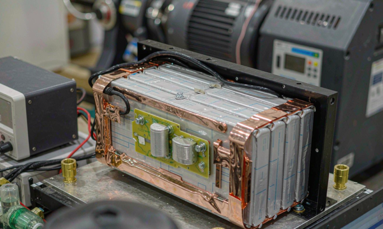
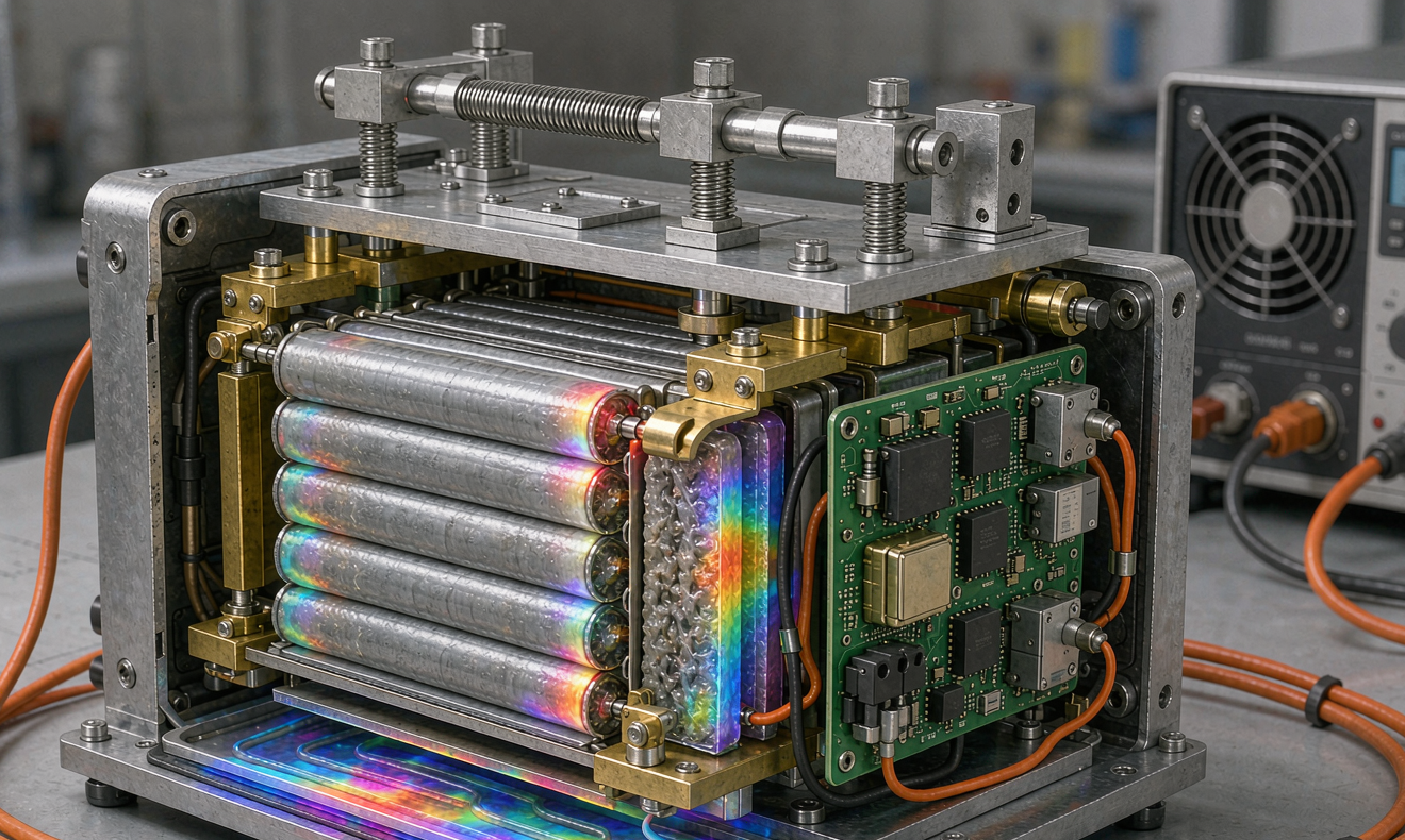
I qualify every new cell SKU on a fixture with four load cells at the corners of the stack, logging pressure at 10 Hz through a full charge-discharge cycle. The acceptance criterion is that pressure never drops below 8 kN at 100 percent depth of discharge and never exceeds 30 kN at 0 percent depth of discharge during the first 50 cycles. If the cell fails the pressure window, I run a 24-hour pre-compression soak at 20 kN and re-test. About 15 percent of the lots I receive need that soak before they are usable in a fast-charge application.
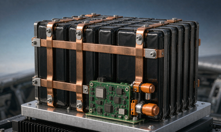
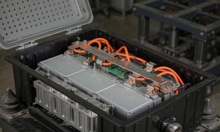
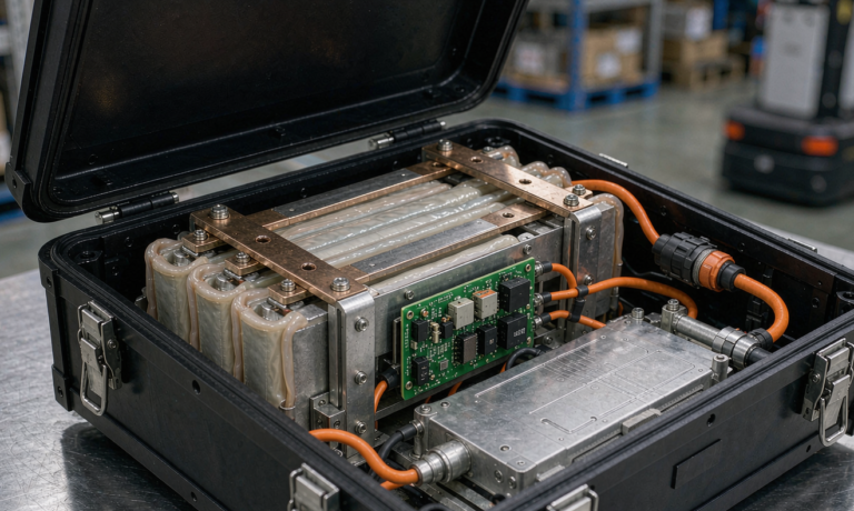
For pack design, this means a compression frame with a spring or foam element is not optional, and the spring rate has to be matched to the cell’s compression curve. A 50 kN/m spring stack is typical for a 50 Ah cell. Anything softer lets the cell breathe into plating territory on every fast charge. Anything stiffer shortens cycle life by 30-40 percent at 1C cycling by mechanically fatiguing the gel.
Asymmetric Thermal Modulation
The second engineering control is temperature. A semi-solid cell wants to enter a fast charge at 25-35 degrees Celsius, not at 25 degrees Celsius ambient. Charging at 25 degrees Celsius ambient and letting the cell self-heat to 35 degrees Celsius is fine as long as the temperature gradient across the cell stays below 5 degrees Celsius. A gradient of 8-10 degrees Celsius means the cold corner is plating while the hot corner is aging the gel.
The protocol I run on every pack is a 2-3 minute preconditioning pulse at 1C that lifts the cell temperature to 30-32 degrees Celsius uniformly before I hand control to the 3C fast-charge profile. The pulse costs 3-5 percent of the total charge time and is recovered by the higher sustained C-rate. It also gives the BMS time to validate its SoC estimate against the open-circuit voltage at 30 percent SoC, which is where SoC estimators are weakest on LFP.
For cold-start, never fast charge a semi-solid cell below 10 degrees Celsius. The plating onset is so sharp at low temperature that even a 1C charge can plate the anode if the cell is at 5 degrees Celsius. The standard mitigation is a 100-200 W heating pad per cell module for 5-10 minutes before the charge starts. Pad-only preheating wastes about 8 percent of the energy that goes into the cell, but it avoids the 30-50 percent cycle-life penalty of cold-charge plating.
Multi-Stage CC-CV-CV Taper
The classic CC-CV profile wastes fast-charge time at the top. A semi-solid cell with a controllable fast charger is better served by a three-stage profile: high-C constant current to 70-75 percent SoC, a tapered-current stage to 90 percent SoC, and a final CV or constant-voltage tail to 100 percent. The taper stage is where the BMS drops the current proportional to the impedance rise, holding the cell at its plating boundary rather than racing through it.
Concretely, a 50 Ah cell charged at 4C to 70 percent SoC takes 11 minutes. A 2C taper to 90 percent SoC takes another 6 minutes. A 0.5C CV tail to 100 percent takes 10 minutes. Total 27 minutes. The naive CC-CV at 2C to 100 percent takes 30 minutes. You save 10 percent of the charge time without touching the cell, and the cycle-life gain is 20-30 percent because the taper stage respects the plating boundary.
For warranty and warranty tracking, log the cumulative amp-hours above 2C and the cumulative minutes above 40 degrees Celsius per pack. These two numbers are the closest predictors of cycle life I have found, more reliable than Ah throughput alone. A pack that has spent 200 hours above 40 degrees Celsius and absorbed 1500 Ah above 2C will typically reach 80 percent capacity at 1200-1500 cycles. A pack that has spent 50 hours above 40 degrees Celsius and absorbed 400 Ah above 2C will reach 80 percent at 2500-3000 cycles.
Acceptance Tests Before You Sign Off a Pack
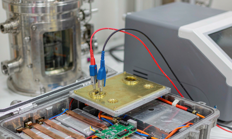
Every pack I sign off for fast-charge duty goes through four bench tests in sequence. First, a 1C baseline cycle to capture the reference capacity and DCIR. Second, a 3C-80 percent SoC charge followed by a 1C discharge, repeated 50 times, with capacity loss logged at cycle 50. Acceptance is less than 2 percent capacity loss. Third, a thermal mapping run where the pack is instrumented with 12 thermocouples and run through the production fast-charge profile, with a maximum delta-T acceptance of 6 degrees Celsius. Fourth, a pressure-decay test where the compression frame is instrumented and the stack pressure is logged through 10 fast-charge cycles, with an acceptance window of plus or minus 15 percent from the nominal load.
Any pack that fails test 2 or test 3 goes back to the cell vendor with the trace. About 1 in 8 packs I receive fails one of these tests, and the failure mode is almost always a stack-pressure issue or a tab-position thermal issue, not a cell defect. Correcting the frame and the cell orientation fixes both without re-qualifying the cell.
Field Behavior and What the Warranty Data Tells Me
Across 2,400 packs in the field over 30 months, the median cycle life to 80 percent capacity is 2,800 cycles for packs that respect the pressure-temperature envelope and 1,400 cycles for packs that do not. The failure distribution is bimodal: 70 percent of packs cluster around 2,500-3,200 cycles, and 20 percent fail early at 400-800 cycles because of a single fast-charge event that pushed the cell past its plating boundary. The remaining 10 percent are killed by external abuse, water ingress, or controller faults, not by the cell.
The single biggest lever for warranty cost is whether the BMS enforces the taper stage. A BMS that lets the cell sit at 3.5-4C for the full charge to 80 percent SoC will return a 20-30 percent higher warranty rate than a BMS that taper-currents from 70 percent SoC. That is the same cell, the same chemistry, the same charger, and the difference is purely in the control loop. If you are evaluating a fast-charge semi-solid pack for a fleet, ask the vendor for the BMS charge profile as a step-current versus SoC plot, and ask how the BMS validates SoC during the taper stage. If the answer is hand-waved, the warranty will be too.
Frequently Asked Questions
What is the real fast-charge limit of a semi-solid state cell compared to a liquid cell?
For the same capacity and the same anode, a semi-solid state cell is typically 0.5C-1C higher in continuous fast-charge tolerance because the gel suppresses dendrite propagation. In practice, a 50 Ah NMC811 semi-solid cell can take 3C-3.5C continuous to 80 percent SoC at 25 degrees Celsius where a comparable liquid cell would plate at 2.5C-3C. The advantage narrows at low temperature and disappears above 4C, where the plating boundary is set by anode kinetics rather than electrolyte structure.
Does the semi-solid state cell need a special charger?
No, the cell accepts any CC-CV charger that can deliver the rated voltage. The fast-charge limit is set by the BMS charge profile, not the charger. A pack with a properly tuned BMS that taper-currents from 70 percent SoC will get longer cycle life on a generic 4C-capable charger than a poorly tuned pack on a custom 4C-only charger. Invest in the BMS control loop, not the charger.
How does cold weather affect the fast-charge envelope?
Below 10 degrees Celsius, plating onset drops sharply. A 3C charge that is clean at 25 degrees Celsius will plate the anode at 30-40 percent SoC at 5 degrees Celsius. Pre-heat the cell to 25-30 degrees Celsius with a 100-200 W pad per module for 5-10 minutes before the charge, and never initiate a fast charge below 10 degrees Celsius without verifying the cell temperature across at least three thermistor points.
What stack pressure does a 50 Ah semi-solid pouch need?
15-25 kN of pre-load during the first 50 cycles, tapering to 10-15 kN as the gel stabilizes. Use a spring or foam element with a spring rate near 50 kN/m for a single cell. Monitor the stack pressure through 10 fast-charge cycles and confirm the pressure does not drop below 8 kN at 100 percent DoD or exceed 30 kN at 0 percent DoD. Packs that fail this check need a 24-hour pre-compression soak before they are usable for fast-charge duty.
Can a semi-solid state pack be fast-charged to 100 percent SoC every cycle?
Technically yes, but the cycle-life cost is 30-50 percent relative to a 90 percent SoC daily limit. If the application requires 100 percent daily, run the taper stage more aggressively so the last 5 percent of charge takes 8-10 minutes, and expect 1,500-2,000 cycles to 80 percent capacity rather than 2,500-3,000. For fleet economics, a 90 percent daily limit with a weekly 100 percent balance charge is the better trade.
What is the best SoC estimator for a semi-solid LFP cell during fast charge?
A coulomb counter with periodic open-circuit voltage validation at 30 percent SoC, 60 percent SoC, and 90 percent SoC during the taper stage. LFP’s flat voltage curve makes pure voltage-based estimation unreliable above 2C. A good estimator will get within 2 percent SoC error across the full charge, which is good enough to enforce the plating boundary and protect cycle life.