Home Energy Storage and EV Charger Load Balancing: Panel Limits, CT Sizing and Charging Schedule Guide
I have lost count of how many times a customer has called me after the electrician left. The panel was full, the utility had quoted a four-figure service upgrade, and the brand-new 48 A wall charger sat in its box because nobody could figure out how to feed it. In almost every one of those cases the right answer was not a bigger service — it was a home energy storage system sitting between the meter and the charger, doing the load balancing that a dumb contactor or a manual “don’t run the dryer while charging” rule was never going to achieve.
I am Karl Huang, Senior lithium battery Engineer at Horizon Power. Over the last decade I have specified battery hardware for residential projects in climates from Shenzhen to Minnesota, and the pattern is the same everywhere: the EV arrives first, the charger gets installed at whatever the panel can spare, and only then does the homeowner discover that 11.5 kW of continuous charging load does not coexist politely with air conditioning, a heat pump water heater and an electric range. This guide is the engineering version of the conversation I have on those calls — panel limits, current-transformer placement, control logic, and the sizing arithmetic that decides whether you need a service upgrade at all.
Why the Panel Becomes the Bottleneck the Moment an EV Arrives
A North American single-family service is a 120/240 V split-phase system. A 200 A main breaker gives you 200 A × 240 V = 48 kVA of apparent power; a 100 A service gives you 24 kVA. That number is not the amount you can add — it is the ceiling for everything running at once. Residential load calculations under NEC Article 220 already assume diversity, but an EV charger is the opposite of diverse: it is a continuous load that can sit at full output for six to eight hours.
Level 2 charging hardware comes in a few standard sizes, and the circuit sizing is where people get burned:
- 7.4 kW (32 A) — needs a 40 A circuit per the 125 % continuous-load rule in NEC 625, typically 8 AWG copper.
- 9.6 kW (40 A) — needs a 50 A circuit, 8 AWG or 6 AWG depending on run length.
- 11.5 kW (48 A) — needs a 60 A circuit, 6 AWG copper is the usual answer.
- 19.2 kW (80 A) — needs a 100 A circuit, 3 AWG copper, and realistically a 400 A service or a load-management system.
Add a 4-ton air conditioner (roughly 4–5 kW running), an electric dryer (5 kW), and a heat pump water heater (4–5 kW when the compressor is on) and a 100 A service is already arithmetic it cannot win. The traditional fixes are a service upgrade (&3,000–$10,000 and a utility coordination queue) or a manual load-shed relay that kills the charger when the house demand spikes. Both work. Neither is what I would specify if the homeowner is already considering a battery.
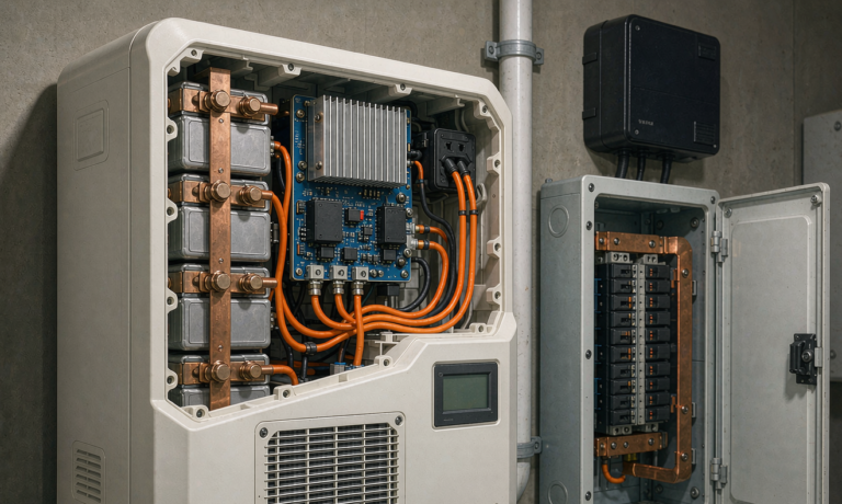
A home battery storage system changes the equation because its inverter is a controllable source. Instead of shedding the EV, the system measures the whole-house current at the service entrance and modulates the charger’s pilot signal so that grid import never exceeds the service limit. The EV still charges, just at whatever current is actually available that minute.
How Dynamic Load Balancing Actually Works
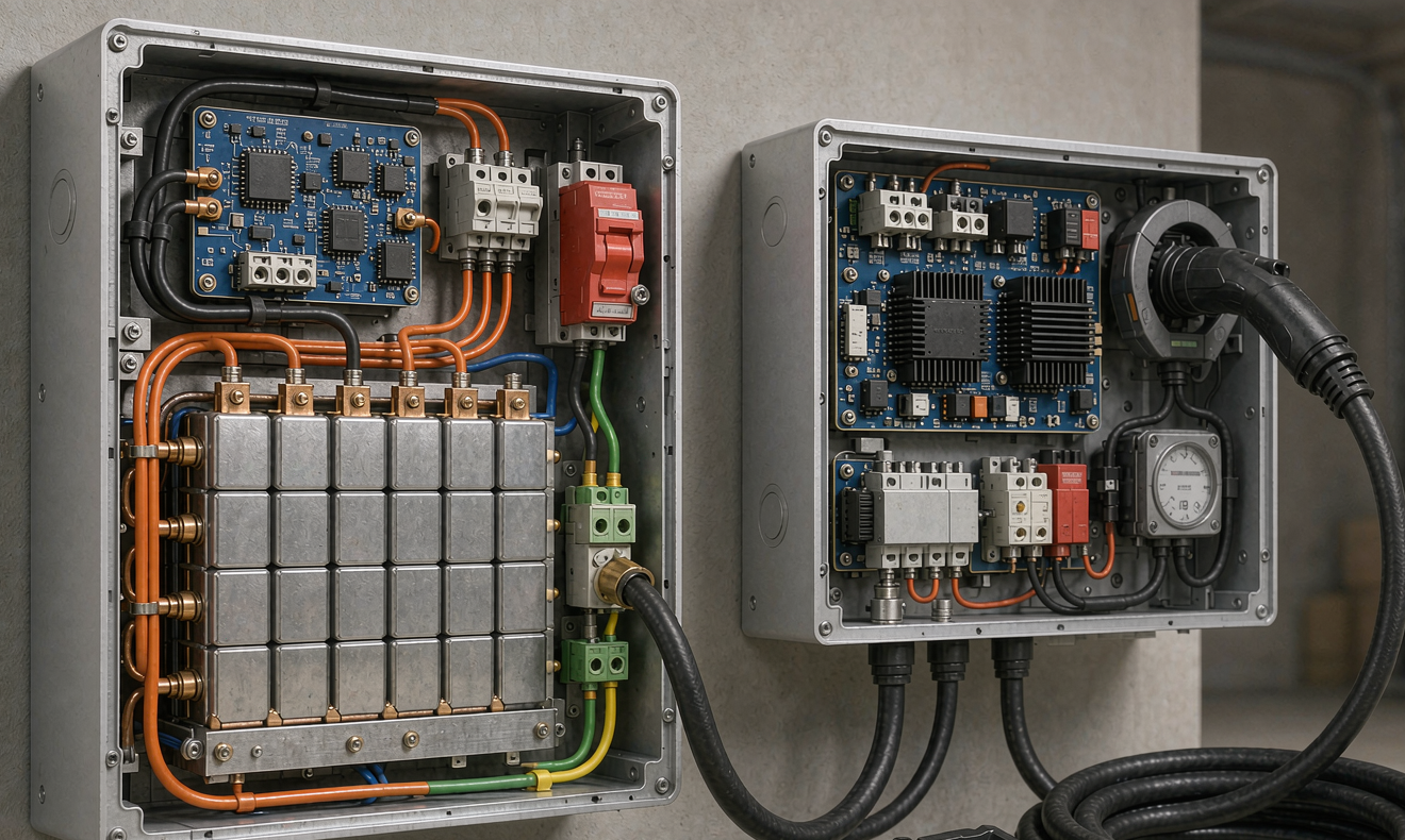
The control loop is simpler than the marketing material suggests. A split-core current transformer (CT) — or, in three-phase markets, three of them — clamps around the service conductors and reports instantaneous import. The energy management controller then solves one inequality every control cycle:
Iavailable = (Iservice limit − Ihouse measured) ÷ 1.25
That result is communicated to the EVSE over the J1772 control pilot as a duty-cycle change, which is how the car learns the maximum current it may draw. Response time matters: a well-implemented loop updates every 1–5 seconds and ramps the pilot in 1 A or 2 A steps rather than slamming between 6 A and 48 A, because abrupt steps upset some onboard chargers and cause nuisance contactor chatter.
Two hardware decisions determine whether this works in the field:
CT Placement and Accuracy Class
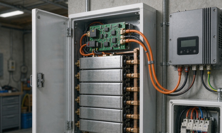
Clamp the CTs on the service conductors between the meter and the first branch breaker, never downstream on a sub-feed. I specify class 1 % or better, with 100 A : 5 A or 333 mV output matched to the meter input, and I insist the installer verify polarity — a reversed CT reports export as import, and the controller will then happily ramp the charger up while the main breaker runs hot. Every commissioning sheet I sign includes a CT polarity check: turn on a known 3–4 kW resistive load and confirm the reading is positive.
Where the Charger Is Fed From
This is the decision that causes the most callback pain. Three options, in the order I usually recommend them:
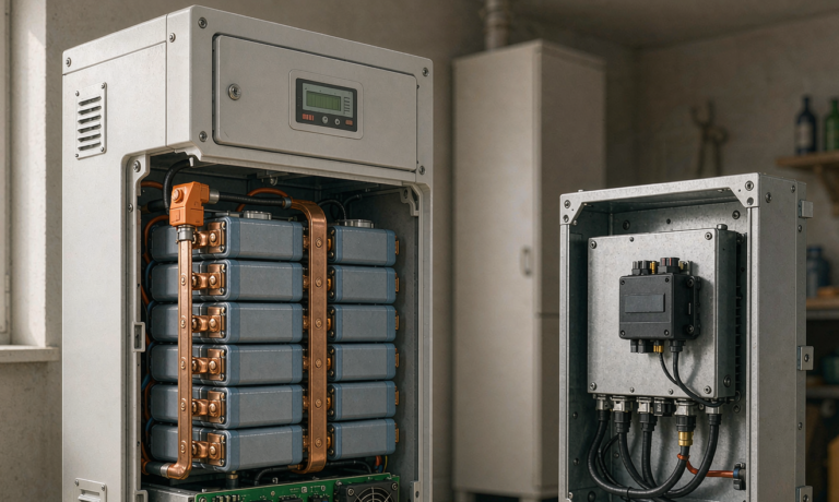
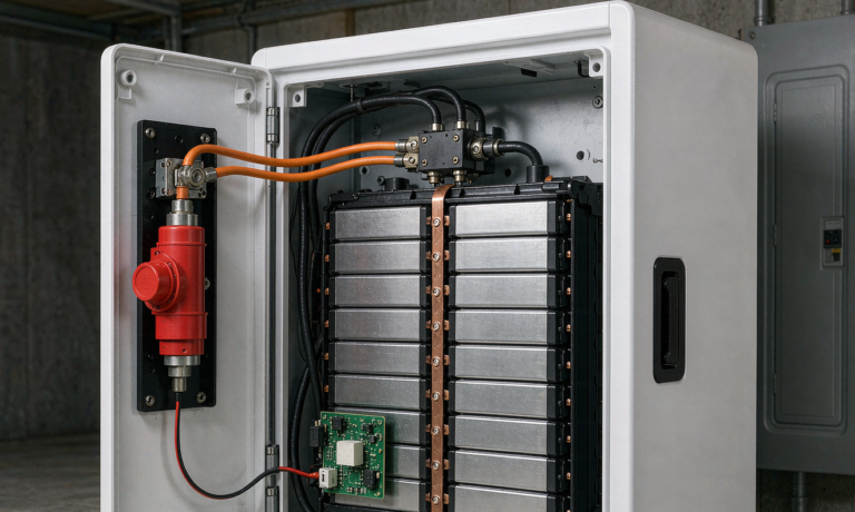
- Charger on the main panel, battery on the main panel. Simplest, cheapest, and the battery inverter can see the charger load through its CTs and back-feed the difference. Whole-home backup covers the charger if it is sized for it.
- Charger on the main panel, battery feeding a backup subpanel. The charger loses power during an outage but load balancing still works in normal operation. This is the most common configuration in retrofits.
- Charger on the backup subpanel. Sounds attractive — charge the car during an outage — but a 48 A charger will flatten a 10 kWh battery in under two hours and frequently trips the inverter on overload. I only approve this with hard current limiting to 16–24 A and an explicit homeowner agreement.
Sizing the home energy storage system Around Charging
Let me walk through the arithmetic I use, because it is the part that gets skipped. Take a house with a 100 A service, an 11.5 kW charger, and a 60 km daily commute in a mid-size EV consuming about 180 Wh/km at the wall.
Daily charging energy: 60 km × 180 Wh/km ÷ 0.90 charger efficiency ≈ 12 kWh delivered from the battery or grid. Spread over a six-hour off-peak window that is roughly 2 kW average, but the car will happily pull 11.5 kW if you let it.
Now the battery. Two constraints govern, and they are different:
- Power constraint. The inverter must cover house base load plus whatever the charger draws. If house base load is 1.5 kW and you want 7.4 kW charging, you need roughly 9 kW of continuous inverter output — a 10 kW class hybrid inverter, with 1.5× surge capability for motor starts.
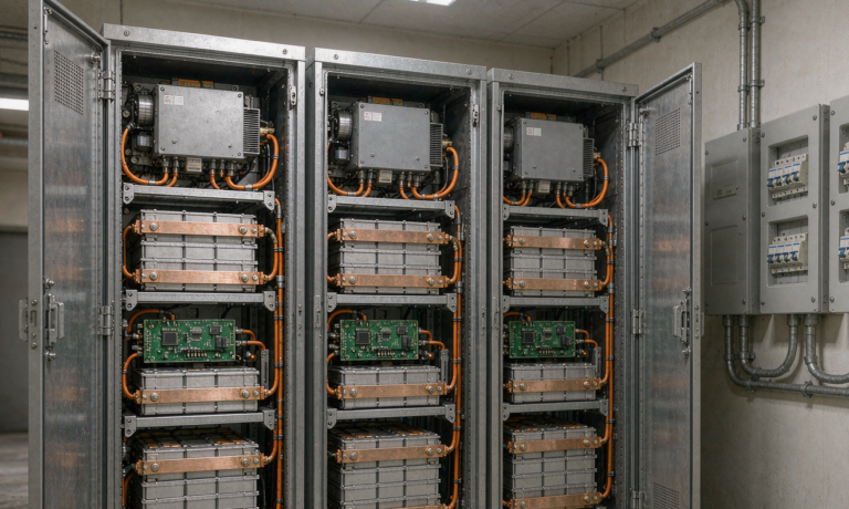
- Energy constraint. 12 kWh of charging plus overnight house consumption. A 10 kWh module covers the car alone with nothing left for backup; 15–20 kWh is where most of my residential designs land.
Usable capacity is not nameplate capacity. LFP modules are specified at 90–95 % usable depth of discharge, so a 15 kWh nameplate pack delivers 13.5–14.3 kWh. Derate further for cold: at −10 °C an unconditioned LFP pack loses roughly 15–25 % of deliverable energy, and below 0 °C it will not accept charge at all until the internal heater (typically 100–300 W) has brought the cells up.
Worth stating plainly: an EV battery is 60–100 kWh. No residential home energy storage system is going to fill it. The right mental model is that the house battery covers daily driving from solar surplus and shaves the peak, while the grid handles the occasional long-trip deep charge. I tell customers to budget for about 80–90 % of annual charging energy coming through the solar-plus-storage path, not 100 %.
Chemistry and Cycle-Life Reality Check
Every residential product I spec today is lithium iron phosphate. LFP gives 90–160 Wh/kg at cell level, 3,000–6,000 cycles to 80 % capacity at 0.5 C and 25 °C, and — the reason it matters in a garage — a thermal runaway onset around 270 °C versus 150–210 °C for NMC. When a pack is mounted three metres from where the family parks, that margin is not academic.
Round-trip efficiency is where the energy actually goes. Cell-level coulombic efficiency is 98–99 %, but the AC-to-AC round trip through a residential hybrid inverter lands at 88–92 %. So moving 12 kWh from midday solar to a 2 a.m. charging session costs you roughly 1–1.5 kWh. That is still usually cheaper than the peak-to-off-peak spread, but it means you should not cycle the house battery purely to arbitrage a 3 ¢/kWh difference — you will spend more of the pack’s cycle budget than the tariff pays for.
A practical cycle budget: 15 kWh usable, 6,000 cycles to 80 %, means roughly 90 MWh of lifetime throughput. At 12 kWh/day of charging support that is about 7,500 days of headroom from the EV alone — the calendar, not the cycles, is what will retire the pack. This is why I push back on customers who want to deep-cycle to 5 % SoC every night for a marginal tariff gain.
If you are weighing sodium-ion for a cold-climate installation, that is a legitimate option worth discussing — sodium cells tolerate lower temperatures on charge and ship at 0 V — but energy density is still 30–40 % below LFP, so the cabinet gets bigger for the same kWh.
Charging Schedule: Getting the Most From Solar and Off-Peak
Load balancing solves the power problem. Scheduling solves the cost problem. A control strategy that has worked well across the projects I have commissioned:
- 10:00–15:00 — solar-assist window. Charge the house battery first, then allow the EV to absorb surplus above a 1–2 kW export floor. Grid export tariffs are often a fraction of the retail rate, so every kWh pushed into the car is worth more than the same kWh sold back.
- 15:00–21:00 — peak avoidance. Battery discharges to cover house load; EV charging is capped at 6–12 A or held entirely. This is where peak demand charges, where they apply, are actually avoided.
- 23:00–06:00 — off-peak fill. Battery recharges, EV resumes at full pilot current, both inside the service limit.
- Winter override. Below 0 °C the pack will not accept charge, so the schedule must leave a preheat window — typically 20–40 minutes at 150–300 W before the bulk charge begins.
One caution on communication standards. Basic J1772 gives you one-way current limiting, which is enough for load balancing. ISO 15118 adds plug-and-charge and, in the -20 revision, bidirectional energy transfer. If vehicle-to-home is on your roadmap, insist on hardware that already carries the certification — retrofitting it later is not a firmware update, it is a new inverter and a new utility interconnection agreement.
Codes, Standards and the Commissioning Tests I Refuse to Skip
Residential storage in North America is governed by a stack that is easy to get wrong: NEC Article 705 for interconnected sources, 706 for the energy storage system itself, 625 for the EVSE, and Article 220 for the load calculation that justifies the whole installation. NFPA 855 sets separation and fire-protection rules, including the widely used 40 kWh per residential unit threshold that changes what fire-rated construction you need. On the product side I require:
- UL 9540 / UL 9540A — system-level and thermal-runaway-propagation testing.
- UL 1973 — battery safety for stationary applications; UL 1642 or IEC 62133-2 at cell level.
- UL 1741 SA / IEEE 1547 — grid-support inverter functions (volt-var, frequency-watt) that many utilities now require before permission to operate.
- IEC 62619 and IEC 62620 — for projects outside North America.
- UN38.3 — transport, still required for anything shipped by road, sea or air.
On site, five tests before I sign off:
- CT polarity and scaling. Known 3–4 kW load, confirm sign and magnitude within 2 %.
- Load-balance ramp. Run the house to 80 % of service rating, then start charging; verify the pilot ramps down and grid import stays under the limit for 15 minutes.
- Overload ride-through. Apply 1.5× inverter rating for 10 s; confirm no nuisance trip and no DC bus sag beyond specification.
- Cold-start behaviour. With the pack below 5 °C, confirm the heater engages and charge current stays at zero until the enable threshold is reached.
- Transfer test. Open the main breaker and confirm the backup subpanel re-energises within the specified 20 ms–2 s window with no back-feed to the grid.
Every one of these has caught a real defect on a job I have been involved with. The CT polarity check in particular has found reversed clamps on roughly one installation in ten.
Frequently Asked Questions
Can a home energy storage system charge my EV during a power outage?
Technically yes, if the charger is on the backup subpanel. Practically, it is a poor trade: a 48 A charger draws 11.5 kW and will empty a 15 kWh pack in about 75 minutes of usable energy. I permit it only with the charger hard-limited to 16–24 A, which gives 4–6 kW and roughly three hours of emergency charging while still leaving capacity for refrigeration and lighting.
What size home battery do I need for an 11.5 kW EV charger?
Power first: house base load plus charger output, plus margin. For a typical 1.5 kW base load with 11.5 kW charging you need about 13 kW of inverter output, which points at a 12–15 kW hybrid unit. Energy second: 15–20 kWh nameplate (13.5–19 kWh usable) covers a 60 km daily commute plus overnight house load. Below 10 kWh you will be importing from the grid on most winter days.
Does EV charging shorten my home battery’s life?
Not meaningfully, if the cycling stays shallow. LFP at 3,000–6,000 cycles to 80 % capacity has far more cycle budget than a daily 12 kWh draw consumes; calendar ageing will retire the pack first. What does shorten life is repeated deep discharge below 10 % SoC and charging below 0 °C without preheat. Keep the operating window at 10–90 % and let the BMS manage thermal limits.
Do I need a main panel upgrade if I am adding both a battery and an EV charger?
Often not, and that is the entire point of load balancing. If the NEC Article 220 load calculation clears the service rating with the charger’s 125 % continuous factor included, a CT-based energy management system is explicitly recognised as an alternative to upsizing. If the calculation fails even with managed charging, a 100 A to 200 A upgrade is the honest answer — do not let anyone sell you around it.
Should the EV charger go on the main panel or the backup panel?
Main panel, in most of my designs. The battery inverter still sees the load through its service-entrance CTs and will back-feed the difference, so load balancing works, and you avoid dumping 11.5 kW onto an inverter that is also carrying the house. Put the charger on the backup panel only if emergency charging is a specific requirement and you accept the current limit that comes with it.
How much of my EV charging can solar plus storage realistically cover?
Plan for 80–90 % of annual charging energy. The gaps are predictable: consecutive cloudy days in winter, long-trip deep charges that exceed the pack’s usable capacity, and cold mornings where the pack cannot accept charge until it has preheated. Anyone promising 100 % self-sufficiency from a residential-sized home energy storage system is selling, not engineering.
Is bidirectional V2H worth waiting for?
It depends entirely on your tariff and your utility’s interconnection rules. The hardware cost premium is real, and ISO 15118-20 capable vehicles are still a minority of the fleet. If you are buying a battery today, specify an inverter with a documented V2H roadmap, but do not defer the solar-and-storage project on the strength of it.
Where I Would Start
If you are standing where most of my customers start — EV delivered, panel full, three quotes in hand — the sequence I recommend is: get a proper Article 220 load calculation, measure two weeks of real interval data at the service entrance, then size the battery to the measured peak rather than the nameplate sum. The measured number is almost always lower than the arithmetic sum, and it is the difference between a 10 kWh system and a 20 kWh one.
At Horizon Power we build custom battery solution hardware for exactly this kind of constrained retrofit, and the packs integrate with the same lithium cell platforms we use across our industrial and drone lithium battery lines. Bring the interval data and the panel schedule, and we can usually tell you within a day whether load balancing saves you the service upgrade.