Semi-Solid State Battery for Medical Devices and Implants
I am Karl Huang, a senior lithium battery engineer, and the two hardest design reviews I sit through every year are not about cars or aircraft. They are about devices that end up inside or against a human body. A drone battery that fails costs a survey contract; a battery inside an implantable neurostimulator costs somebody a second surgery. That difference drives every decision below, and it is why I have spent the last three years qualifying a semi-solid state battery for medical device and implant programmes rather than chasing the highest number on a datasheet.
This article covers what changes compared with a conventional lithium battery, what does not change at all, the standards that actually gate your launch, and the acceptance tests I refuse to skip on a medical build.
Two Very Different Product Classes Hide Inside the Same Phrase
The first thing I do in a medical programme is force a decision that marketing documents usually blur. There are two classes, and they share almost nothing.
Class one is implantable: neurostimulators, cochlear implants, implantable cardioverter defibrillators, drug pumps and ventricular assist controllers. These sit under ISO 14708 and, in the European Union, under MDR 2017/745 as Class III devices. The enclosure must be hermetic, the chemistry must survive a decade at 37 °C in a saline-equivalent environment with no service access, and every material that could touch tissue is screened under ISO 10993. Weight matters less than volume: the surgeon has a fixed pocket, and a pack that is 15 % thicker does not fit.
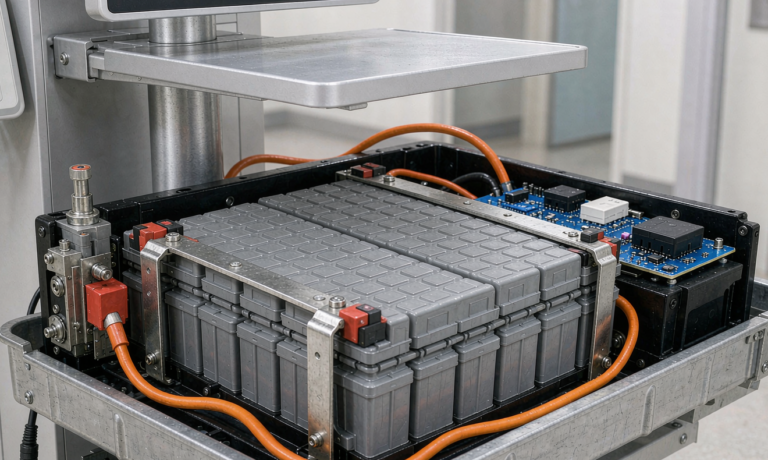
Class two is patient-adjacent and portable medical equipment: ventilators, infusion pumps, defibrillators, portable ultrasound, monitors, powered surgical tools and mobile carts. These fall under IEC 60601-1 (edition 3.2) and IEC 60601-1-2 edition 4 for electromagnetic compatibility. The pack is field-replaceable, the enclosure is plastic or aluminium rather than titanium, and the failure mode is managed rather than eliminated.
Why this matters for chemistry: a semi-solid state battery brings its biggest advantage to class one, where reduced free electrolyte and a wider abuse margin earn real risk-management credit under ISO 14971. For class two it is usually a cost decision, because a lithium iron phosphate pack already clears IEC 60601-1 at a lower unit price.
Energy Density: Why Implant Engineers Buy Watt-Hours per Litre
Automotive engineers quote watt-hours per kilogram. Implant engineers quote watt-hours per litre, because the volume budget is fixed long before I get the call. On the cells I currently qualify:
- Semi-solid state cell: 270–340 Wh/kg, 500–650 Wh/L
- Conventional NMC 811 liquid cell: 240–280 Wh/kg, 550–700 Wh/L
- LFP cell: 150–180 Wh/kg, 350–400 Wh/L
Notice the semi-solid cell wins decisively on gravimetric density but only matches on volumetric density. That is honest and important. If your device is volume-limited — and every implant is — a semi-solid state battery does not automatically shrink the device. What it does is keep the same volume at roughly 20–30 % less mass, which for a wearable or an external controller worn on the body is a genuine comfort and fixation benefit.
At pack level the picture improves, because the safety argument lets you remove containment mass: on a recent wearable controller we deleted a 1.0 mm aerogel blanket and part of the steel barrier and still cleared IEC 60601-1 single-fault testing.
Leakage, Hermeticity and the Free-Electrolyte Question
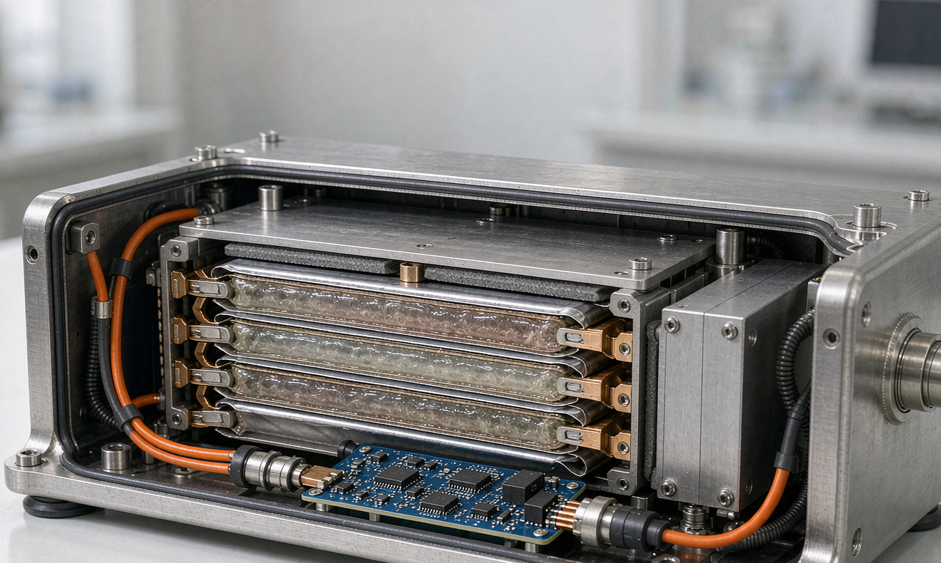
A conventional lithium-ion cell carries roughly 20–30 wt% free liquid electrolyte; a semi-solid state battery typically carries 8–14 wt%, with the remainder immobilised in a gel or oxide-filled separator structure. That is not zero, and I push back hard on vendors who imply it is. But it changes the failure mode in a way a risk-management file can legitimately credit.
Puncture a conventional pouch cell in the lab and the electrolyte wicks and pools within seconds. Puncture a semi-solid pouch of the same format and the expelled volume is smaller and does not run. For an implant, that means a cell breach is far less likely to produce bulk chemical exposure inside a tissue pocket. It does not remove the hermetic-enclosure requirement, and ISO 14708-1 will not let you argue otherwise.
My hermeticity specification on implant builds is unchanged by chemistry:
- Laser-welded titanium (grade 2 or Ti-6Al-4V) or 316L stainless enclosure, 0.3–0.5 mm wall
- Helium leak rate below 1 × 10⁻⁹ Pa·m3/s, verified per MIL-STD-883 test method 1014 condition A2, re-checked after every mechanical and thermal shock sequence
- Glass-to-metal sealed feedthroughs, never polymer-grommeted feedthroughs, on any conductor crossing the boundary
- 100 % helium bombing on production units, plus a 10 % sample opened for internal inspection after accelerated aging
Thermal Behaviour: What the Gel Layer Really Buys You
On our accelerating rate calorimetry bench, the self-heating onset temperature tells the story:
- Semi-solid state cell: 165–180 °C onset, peak thermal runaway 550–650 °C
- NMC 811 liquid cell: 110–140 °C onset, peak 700–850 °C
- LFP cell: 250 °C onset, peak 450–550 °C
That 30–50 K shift is the argument for a semi-solid state battery in patient-contact equipment. It does not make the cell non-flammable, and IEC 60601-1 clause 11 single-fault testing remains mandatory. What I do get is time: in nail-penetration testing on implantable-format pouch cells, the interval from penetration to external case breach moved from 40–70 seconds on a liquid equivalent to 4–8 minutes on the semi-solid part. On a device strapped to a patient, that window is the difference between a controlled shutdown and a burn.
Surface temperature is the other gate. Touchable surfaces are limited to 48 °C under IEC 60601-1 in normal condition, and applied parts in continuous contact are held tighter. With a 0.3 C discharge at 25 °C ambient our external packs sit at 34–39 °C with a passive aluminium spreader; at 40 °C ambient they reach 52 °C without one and 44 °C with one. That is a week-two design decision, not a week-twenty one.
Cycle Life and Calendar Aging at 37 °C
Implantable duty cycles look nothing like automotive ones. A neurostimulator draws a 20–80 µA baseline with periodic stimulation bursts, and a rechargeable spinal cord stimulator sees shallow 5–15 % cycles weekly. An infusion pump or ventilator is the opposite: deep cycles, sometimes daily, over a 3–5 year service life.
Numbers I use from our own qualification data:
- Full 100 % depth of discharge cycling at 25 °C: 1,000–1,500 cycles to 80 % capacity for the semi-solid cells we qualify, against 800–1,200 for a comparable liquid NMC cell
- Shallow 10 % depth of discharge cycling: 10,000–15,000 equivalent micro-cycles before the same 80 % threshold
- Calendar fade at 25 °C and 50 % state of charge: 1.5–2.5 % capacity loss per year
- Calendar fade at 37 °C and 50 % state of charge: 3.0–4.5 % per year, roughly double, consistent with an Arrhenius Q10 near 2
That last line is why I argue for conservative implant sizing. A pack sized to deliver exactly the rated capacity on day one falls below the 80 % end-of-life threshold in year six or seven purely from calendar fade, independent of cycling. My rule is to size to 80 % of nominal capacity on day one so the device still meets full specification at end of declared service life.
State of charge during storage matters as much: we ship at 30 % as UN38.3 requires and hold incoming cells at 30–50 % and 15 °C. Cells stored at 100 % and 37 °C lost 8–11 % of capacity in nine months in our own shelf-life study.
The Standards That Actually Gate a Launch
This is the list I put in front of every customer on day one, because a surprising number of battery suppliers can quote UN38.3 and nothing else:
- UN38.3 — transport; cells at not more than 30 % state of charge for air shipment.
- IEC 62133-2 — baseline safety of sealed portable secondary lithium cells and batteries.
- IEC 60601-1 (ed. 3.2) — medical electrical equipment safety, including clause 15.4.3 on lithium batteries and clause 11 single-fault temperatures.
- IEC 60601-1-2 (ed. 4) — electromagnetic compatibility; your BMS converter must coexist with ECG front-ends resolving microvolt signals.
- ISO 14971 — risk management; every hazard you claim the gel layer mitigates needs verification evidence here.
- ISO 13485 — quality system for both the cell supplier and the pack line.
- ISO 10993-1 — biological evaluation, mandatory for implant contact.
- ISO 14708-1 and the device-specific part (-2 cochlear, -3 neurostimulators, -6 active implants).
- IEC 60086-4 — primary lithium implants (Li-CFx or Li-MnO2), still the majority of high-reliability implants.
- FDA 510(k) or PMA, and EU MDR 2017/745 — market access, where reviewers read the battery section closely.
A semi-solid state battery does not come with a regulatory shortcut. It is assessed as a lithium battery with better abuse data. Budget the full qualification programme.
Sizing a custom battery solution for Portable Medical Equipment
For class two equipment the arithmetic is identical whatever the chemistry. Required nameplate energy is:
E = P × t / (DoD × η × EOL)
Worked example from a transport ventilator programme: 75 W average draw, 6 hours of required run time, 90 % allowable depth of discharge, 92 % system efficiency including the DC-DC stage, and an 80 % end-of-life capacity floor.
- 75 W × 6 h = 450 Wh delivered
- 450 / (0.90 × 0.92 × 0.80) = 679 Wh
- Select an 800 Wh nominal pack, which lands the day-one depth of discharge near 76 % and holds specification through end of life
On a custom battery solution for a mobile medical cart the load is lumpier: 250–600 W for the cart, plus a 45–70 W ultrasound and a 15–35 W monitor over an 8–12 hour shift. I size those to 1.2–1.5 kWh and always specify a hot-swap second bay.
Two requirements catch teams out. Means of patient protection is usually 2 MOPP, which means 4,000 VAC dielectric withstand between the battery output and any applied part. And the BMS has to keep its switching converter out of the 0.5–150 Hz band where ECG lives; I specify a fixed-frequency converter above 300 kHz with spread-spectrum disabled and verify with conducted emissions sweeps under IEC 60601-1-2.
Manufacturing Controls and Traceability
Medical builds are where a good cell can be wasted by a mediocre line. The controls I hold on a semi-solid medical pack:
- Dry room at −40 °C dew point or better; ISO 14644-1 Class 7 at the fill and closing station
- 100 % cell-level traceability from electrode coating lot to pack serial, retained for service life plus ten years
- Laser weld windows qualified by design of experiments, with pull-test and cross-section verification
- X-ray inspection of every tab stack before enclosure closing
- Helium leak test on 100 % of hermetic enclosures
- End-of-line: 500 V insulation resistance above 100 MΩ (under 10 MΩ is rejected and the pack torn down), 2 hour rest with cell delta under 30 mV, and a 0.2 C capacity check returning at least 95 % of nameplate
Stack pressure is the semi-solid-specific control liquid lines do not run. Semi-solid cells need a defined compressive load, typically 0.1–0.5 MPa, held by a compliant foam or spring element that survives ten years of thermal cycling. Get it wrong and cycle life drops 30–50 % with no visible defect.
Frequently Asked Questions
How long does a semi-solid state battery last inside the body?
For an implantable rechargeable pack I plan against 5–10 years of declared service life, limited by calendar fade rather than cycling. At 37 °C and 50 % state of charge we measure 3.0–4.5 % capacity loss per year, so a pack sized to 80 % of nominal on day one still meets full specification at year seven. Primary lithium cells under IEC 60086-4 remain the safer choice for very low drain implants needing 10–15 years.
Can a rechargeable implant be charged through the skin without heating tissue?
Yes, but the limit is tissue heating, not the cell. Inductive charging at 100–300 kHz is normally capped so no tissue exceeds a 2 K rise, which typically means 2–5 W delivered and 1–3 hour charge times. A semi-solid state battery helps here because its end-of-life impedance rise is lower, so less coupled energy becomes heat.
Does the gel electrolyte leak if the pouch is punctured?
It leaks far less. Free liquid content drops from 20–30 wt% in a conventional cell to 8–14 wt% in a semi-solid state battery, and in our puncture testing the expelled material pools rather than wicks. It is not zero, which is why ISO 14708-1 still mandates a hermetic enclosure with a helium-verified seal on any implant.
What standards apply to a semi-solid state battery in a medical device?
UN38.3 for transport, IEC 62133-2 for cell and pack safety, IEC 60601-1 and IEC 60601-1-2 for the equipment, ISO 14971 for risk management, ISO 13485 for the quality system, and for implants ISO 10993-1 plus ISO 14708-1 and the relevant device-specific part. Market access then runs through FDA 510(k) or PMA and EU MDR 2017/745.
Is 37 °C body temperature a problem for calendar life?
It roughly doubles the fade rate compared with 25 °C storage, because the dominant aging mechanism follows an Arrhenius relationship with a Q10 near 2. Practically, budget 3.0–4.5 % capacity loss per year at 50 % state of charge and size the pack so the device still meets specification at end of declared service life, not on day one.
How much does it cost to qualify a medical battery pack?
For a class two device I budget 60,000–150,000 USD and 9–15 months for cell qualification, pack design, IEC 60601-1 and EMC testing, and the documentation package. For an implant, plan on 250,000 USD and 18–30 months, driven by biocompatibility, hermeticity validation and accelerated life testing. Semi-solid chemistry adds 10–20 % to cell cost and very little to qualification cost.
Can a medical device with a semi-solid state battery be shipped by air?
Yes, with the same UN38.3 test summary every lithium battery requires and cells at not more than 30 % state of charge. Devices installed in equipment follow UN3481 packing instruction P967 section II; spare packs ship as UN3480. The semi-solid construction does not change the classification.
When should I choose LFP instead of a semi-solid state battery?
Choose LFP when the device is volume-tolerant, cost-sensitive and cart-mounted: infusion pumps, monitors, carts. LFP gives 4,000–6,000 cycles, a 250 °C self-heating onset and the lowest cost per watt-hour. Choose a semi-solid state battery when mass is constrained, when the device is worn on the body, or when the risk file needs the extra abuse margin.
What I Tell Customers at the End of the Review
A semi-solid state battery is the right answer for a specific slice of medical products: implants where volume is fixed and mass matters, wearable controllers, and any device where the risk-management file benefits from a higher abuse threshold. It is not cheaper than LFP and it will not shorten your regulatory timeline. The decisions that decide whether your programme succeeds are made in the first month — device class, volume-limited or mass-limited, and whether your cell supplier can produce ISO 13485 documentation with ten-year traceability. Get those right and the rest is engineering you already know how to do.
Further Reading
References