Battery Solution for Portable Military Communications: Pack Sizing, MIL-STD Compliance and Power Budget Guide
A manpack radio that goes silent in the third hour of a 24-hour mission is a logistics failure before it is an electronics failure. In my work at Horizon Power on rugged power supplies for tactical communications, I have seen exactly that pattern: the radio firmware is fine, the antenna is fine, but the battery solution for portable military communication has been designed like a commercial walkie-talkie pack rather than a field-deployed platform. The fix is rarely exotic chemistry. It is the unglamorous work of power budgeting against a real duty cycle, sizing cells for -32 °C cold start and 71 °C solar soak, validating the BMS against lithium plating at high charge current, and tying every claim to MIL-STD-810H, MIL-STD-461G, and the UN38.3 transport chain. This guide walks through how I specify a tactical radio battery solution from the first stakeholder meeting to the final acceptance test, so procurement engineers and program managers can run a comparable design review on any vendor proposal.
What “portable military communications” actually means in a power spec
Portable military communications is a deceptively broad term. The pack that drives a 5 W handheld radio for a squad member patrolling a perimeter is nothing like the pack that sits on the back of a 50 W manpack used by a forward observer, and neither resembles the buffer module that rides on a vehicle adapter and bridges engine cranking dips. Before any cell is selected, the spec has to call out the platform, the duty cycle, and the operational envelope.
The four reference architectures I see most often are:
- Handheld radio packs — typically 7.2 V or 10.8 V nominal, 2.6 Ah to 4.5 Ah, removable, hot-swap not required, replaceable in the field without tools. Drop test from 1.5 m onto concrete is mandatory.
- Manpack radio batteries — 14.4 V or 25.2 V nominal, 6 Ah to 12 Ah, clipped to the rear of the radio frame, must support a 12 h patrol at a 10/40/10 duty cycle (10 % transmit at full power, 40 % receive, 10 % standby, 40 % off). Cold start at -32 °C is mandatory in cold-region operations.
- Vehicle adapter / vehicular amplifier power supplies — 26.4 V or 28.8 V nominal, 20 Ah to 60 Ah, mounted inside a vehicle with MIL-STD-1275 surge protection. These typically share chassis with a custom battery pack buffer module that absorbs 100 V cranking transients.
- Network backbone and SATCOM manpack nodes — 25.2 V to 50.4 V nominal, 8 Ah to 30 Ah, paired with a hot-swap BB-2590 form factor or a vendor-specific rugged sled. These may run a small battery solutions stack with an active balancer to keep parallel strings within 50 mV during sustained 2 C pulses.
Each of these is a different battery solution, not just a different sticker. The cells, the BMS, the housing, the connector system, and the test program all change. A common procurement mistake is to write a single specification for all four and then let the vendor substitute. Insist on one specification per platform, and require a deviation list if substitution is proposed.
Chemistry choice: why LFP is winning tactical manpacks
Most tactical radio programs I have worked on this year have moved away from LiCoO2 and even high-Ni NMC toward lithium iron phosphate for the primary manpack string, with NMC 811 still acceptable for handheld packs where energy density per kilogram dominates. LFP delivers three things that tactical users care about more than specific energy:
- Thermal runaway margin. LFP cells self-heating onset is around 180–220 °C with thermal runaway above 250 °C; NMC 811 typically self-heats at 110–140 °C and runs away above 200 °C. In a pack that sits in a desert vehicle cabin at 71 °C ambient and is then rapid-charged by a generator, that 60 °C margin is the difference between a cell venting and a pack venting.
- Cycle life at high depth of discharge. LFP routinely delivers 2,500–4,000 cycles at 80 % DOD, against 800–1,500 for NMC. A manpack that is charged nightly on a six-year program thus lasts the full term without a mid-life cell replacement.
- Flat voltage curve. The 3.2 V nominal plateau means transmit power stays in spec from 90 % down to 20 % state of charge. NMC sags noticeably below 30 % SOC, which causes the radio’s automatic power control to step down RF output just when the operator needs range.
Where NMC still wins is handheld radio energy density. A soldier carries fewer batteries when the pack is 14 % lighter, and at the squad level, weight is a clinical safety issue. The compromise I typically spec is NMC 811 for handheld packs with a high-C BMS and a hard upper voltage limit of 4.15 V per cell, then LFP for everything manpack and above.
Pack sizing against a 24-hour mission budget
Sizing a tactical radio battery solution starts with a duty cycle, not a marketing watt-hour number. The standard military manpack budget assumes a 10/40/10 profile: 10 % transmit at full rated RF power, 40 % receive, 10 % idle listening, and 40 % off. At 50 W RF output with a typical 60 % DC-to-RF efficiency, the radio draws about 84 W from the battery on transmit. Receive is 4–6 W, idle is 1.5 W, off is leakage on the order of 200 µA.
Worked example for a 12-hour patrol with a 50 W manpack on a 25.2 V LFP pack:
- Transmit energy: 0.10 × 12 h × 84 W = 100.8 Wh
- Receive energy: 0.40 × 12 h × 5 W = 24 Wh
- Idle energy: 0.10 × 12 h × 1.5 W = 1.8 Wh
- Off leakage: 0.40 × 12 h × 0.005 W ≈ 0.02 Wh
- Total: ≈ 126.6 Wh, plus 20 % margin for end-of-life derating and cold-temperature loss = ≈ 152 Wh
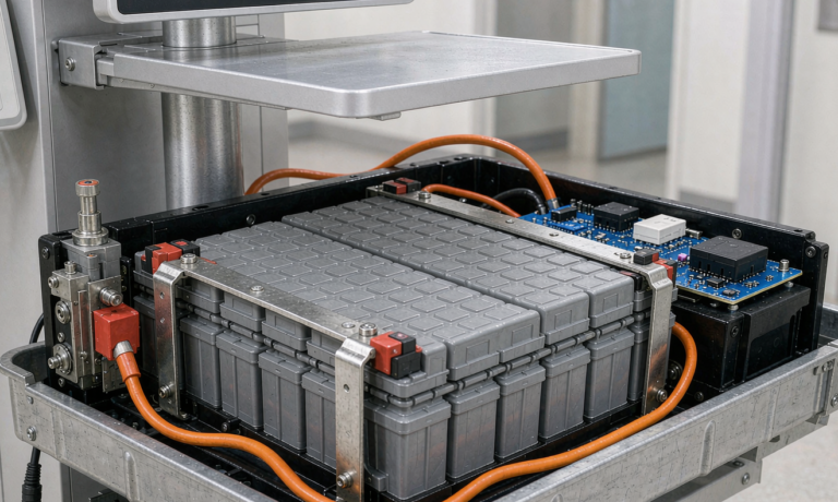
At 25.2 V nominal that is 6 Ah of usable capacity, which translates to roughly a 7 Ah nameplate LFP pack to keep DOD at 85 % over a six-year service life. Two of these packs at 1.4 kg each ride on the radio’s rear clip and can be hot-swapped at a halt in under three seconds. The hot-swap contact block is a 50 A-rated rugged connector with gold-plated pins, and the BMS on each pack includes a precharge circuit so the swap does not arc-weld the contact pins.
Environmental hardening against MIL-STD-810H
MIL-STD-810H is not a single test. It is a menu of method numbers that the program manager selects based on the operational lifecycle. For a manpack that will see temperate and arctic deployments, the typical profile I require is:
- Method 500.6 — Low temperature operation and storage at -32 °C; the pack must deliver at least 70 % of rated capacity at this temperature after a 4 h soak.
- Method 501.7 — High temperature operation at +55 °C, storage at +71 °C, and a 3-cycle rapid thermal shock between -32 °C and +71 °C within 5 min.
- Method 502.7 — Combined temperature-humidity cycling, 30 days at 95 % non-condensing relative humidity with temperature swings between 30 °C and 60 °C.
- Method 514.8 — Random vibration, three axes, 1.04 g²/Hz for 1 h per axis, simulating a vehicle-borne manpack. After vibration, the pack must show no capacity loss greater than 3 % and no BMS fault.
- Method 516.8 — Shock, 40 g, 11 ms half-sine, three axes, six directions. Drop test from 1.5 m onto plywood over concrete on six faces, three edges, one corner.
- Method 506.6 — Rain and water immersion, 1 m for 30 min, IP67 minimum.
- Method 510.7 — Sand and dust, blowing dust 1.7 m/s for 6 h plus settling dust for 6 h.
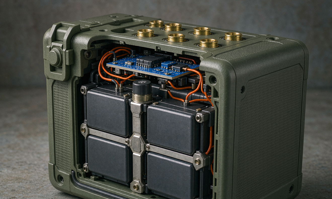
Each of these has a real engineering consequence. The -32 °C operation test drives the choice of low-temperature electrolyte (typically LiPF6 in EC/EMC/DMC with 5–10 % FEC additive) and forces the BMS to disable charging below 0 °C to prevent lithium plating on graphite anodes. The 1.5 m drop test forces the housing to use a glass-filled nylon or magnesium internal frame rather than a thin-wall aluminum shell. The water immersion test forces the BMS connector to be a sealed IP67 automotive-style plug with a secondary gasket at the housing seam.
Electrical protection and BMS design
The BMS is the part of the battery solution that fails first if the spec is generic. For a tactical radio pack, I require at minimum:
- Cell-level protection — over-voltage (per-cell cutoff 3.65 V for LFP, 4.20 V for NMC), under-voltage (2.50 V LFP, 2.80 V NMC), over-current discharge (limit at 2 C continuous, hard cutoff at 3 C), over-current charge (limit at 1 C, hard cutoff at 1.5 C), short-circuit (hard cutoff within 200 µs of detection), and overtemperature (charge cutoff 60 °C, discharge cutoff 75 °C).
- Pack-level protection — reverse polarity via MOSFET body diode or Schottky, ESD to ±15 kV air discharge per IEC 61000-4-2, surge immunity to ±2 kV per IEC 61000-4-5, and conducted RF immunity per MIL-STD-461G CE102 and RE102.
- State of charge and state of health — coulomb counting with periodic OCV anchor, capacity learning every full charge cycle, and SoH reported as both percent of nameplate and internal resistance trend.
- Communication — SMBus v1.1 with optional MIL-STD-1553 interface for vehicles, plus an analog state-of-charge pin that the radio can read without an SMBus stack.
- Data logging — minimum 30 days of time-stamped events including charge, discharge, fault, temperature extremes, and BMS resets. Black box data must survive a 1.5 m drop and a 30-day 71 °C soak.
The BMS firmware has to be locked at the factory with a signed image. Field reprogramming is a security boundary the program office has to call out, and the BMS has to reject any unsigned image even if the radio otherwise accepts it. I have seen more than one tactical radio program held in test for an extra quarter because the BMS firmware was field-flashable without authentication.
Compliance roadmap and certifications
No tactical radio battery solution ships without a paper trail. The minimum set I build into every spec is:
- UN38.3 — T1 to T8 altitude, thermal, vibration, shock, external short, impact, overcharge, and forced discharge tests. Required for any lithium battery transported by air or sea, including military airlift.
- MIL-STD-810H — environmental methods as listed above.
- MIL-STD-461G — conducted and radiated emissions and susceptibility for the BMS and any integrated charger.
- IEC 62133-2 — secondary lithium cells for portable applications, used by NATO stock codification.
- UL 1973 — stationary battery standard, often referenced for fixed and vehicular applications.
- UL 2054 / UL 1642 — household and commercial battery packs, plus cell-level.
- IEEE 1625 / IEEE 1725 — quality and reliability of lithium batteries for portable computing, used as a reference even for radios because the test methodology transfers cleanly.
The paperwork has to be ready before the first production unit ships, not after. The single longest pole in any tactical battery qualification is usually the UN38.3 T6 impact and T7 overcharge tests, which require 30 days of pre-conditioning cycles before the destructive runs.
Acceptance test plan
Each production pack should be acceptance-tested before it ships. The five-test protocol I run on every lot is:
- 500 V insulation resistance between the high-voltage terminals and the housing ground. Reject below 10 MΩ; warn between 10 MΩ and 100 MΩ; accept above 100 MΩ.
- Full charge rest — charge at 0.5 C to the manufacturer’s specified cutoff, rest 2 h, measure cell-to-cell voltage deviation. Reject any pack where the deviation exceeds 30 mV per cell; flag any pack between 15 mV and 30 mV for bench-level rebalancing.
- Capacity verification at 0.2 C constant current discharge from full charge to the manufacturer’s cutoff voltage. Reject any pack delivering less than 95 % of rated capacity; flag any pack between 95 % and 100 % for trending.
- Pulse load test — apply a 2 C pulse for 10 s at 50 % SOC and verify the voltage sag stays within the radio’s brownout threshold, typically 21 V on a 25.2 V system. Reject any pack where sag exceeds 4 %.
- Protection function test — verify each BMS protection trips at the specified threshold. Reject if any protection fails to trip within the specified response time, or if any protection trips at a threshold outside the specified band.
For the first article of every lot, add a full mission-profile discharge test that runs the pack through the 10/40/10 duty cycle to confirm the energy budget. Reject any first article that delivers less than 90 % of the calculated mission energy.
Total cost of ownership and lifecycle
A tactical manpack that costs $1,800 per pack and is replaced once over a six-year program has a true cost of ownership of roughly $300 per pack per year when amortized across the fleet. The cheapest way to bring that number down is to extend cycle life. LFP delivers that for free at the cell level, but the BMS, the housing, and the connector are still the failure points. Spec the connector to 5,000 mate cycles. Spec the housing to IP67 after 50 drop tests. Spec the BMS electrolytic capacitors to 105 °C rated, 10,000 h life.
Storage is the other lifecycle cost driver. A pack stored at 100 % SOC at 35 °C loses roughly 3–6 % capacity per year. A pack stored at 50 % SOC at 20 °C loses less than 1 % per year. Issue each pack with a storage state of 40–60 % and a storage temperature window of -10 °C to +35 °C, and program the radio’s charger to refuse a long-term float charge above 80 % SOC. This single decision typically doubles calendar life for both LFP and NMC.
Frequently asked questions
What is the best battery chemistry for a manpack radio?
LFP for manpack and above, where cycle life, thermal margin, and a flat voltage curve matter most. NMC 811 still has a place in handheld radios where energy density per kilogram dominates and the pack is small enough that a thermal runaway event is contained.
How cold can a tactical radio battery operate?
-32 °C is the standard MIL-STD-810H cold operation target. LFP cells with low-temperature electrolyte deliver roughly 70–80 % of rated capacity at this temperature. Charging must be disabled below 0 °C to prevent lithium plating.
How hot can a tactical radio battery operate?
Discharge up to +71 °C storage and +55 °C continuous operation is typical. The pack must be designed so the cell surface temperature does not exceed 60 °C during 1 C discharge at 55 °C ambient. Active cooling is rarely available, so derating transmit power or adding a thermal mass is the usual answer.
Are tactical radio batteries hot-swappable?
Manpack packs typically are, with a rugged connector rated to 5,000 mate cycles and a precharge circuit to limit inrush current. Handheld packs are usually cold-swapped with the radio powered down, because the connector is too small for a precharge circuit.
How long do these batteries last in storage?
Stored at 50 % SOC between -10 °C and +35 °C, an LFP tactical pack loses less than 1 % capacity per year. Stored fully charged at 35 °C, it loses 3–6 % per year. Always issue packs at 50 % SOC and refuse long-term float above 80 %.
What is the most common cause of field rejection?
Cell-to-cell voltage imbalance after long storage. A pack that sits for 90 days at 30 % SOC comes off the shelf with 60–80 mV of imbalance. The fix is a bench-level equalization cycle, not a pack replacement, and the acceptance test has to be designed to catch this before the pack leaves the warehouse.
Can a tactical radio battery be repaired in the field?
Yes for housing, connector, and BMS board swaps. No for cell-level repair — the cell stack is glued and welded and is replaced as a unit. A field-repair kit with a spare BMS board and a spare housing is far cheaper than a cell-level repair station.
How do you prevent counterfeit cells in a tactical pack?
Source from manufacturers with NATO stock numbers, require lot traceability all the way to the cell supplier, and include a capacity learning step in the BMS that flags any cell that does not match the family signature. The single most reliable defense is an audit of the cell manufacturer’s QC records every six months.
A well-spec’d tactical communications battery solution is not the result of an exotic chemistry or a clever BMS trick. It is the result of a clean power budget against a real mission profile, an honest environmental test program against MIL-STD-810H, a BMS with the protections and data logging the program office actually needs, and a supply chain that ties every cell back to a traceable manufacturer. Run that design review once and the same template scales across handheld, manpack, vehicular, and SATCOM platforms without re-inventing the qualification program each time. At Horizon Power, that is exactly the kind of custom battery solution work our defense and industrial communications customers come back to us for, and it is the same engineering discipline we apply to our lithium battery and drone lithium battery programs.