Lithium Battery Charger CAN Bus Communication and Protocol Integration
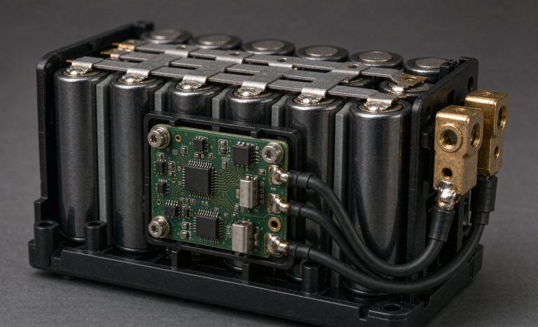
When a customer asks me to integrate a smart lithium battery charger into a battery management system, the conversation quickly moves away from volts and amps and onto the bus. I am Karl Huang, Senior Lithium Battery Engineer at Horizon Power, and I have spent the last decade closing the gap between charger firmware and pack telemetry. A lithium battery pack that cannot tell its charger what is happening is a pack that charges on assumptions. CAN bus is the industrial standard that lets the battery and the charger speak the same language in real time. In this guide I walk through how we wire, handshake, and validate CAN bus communication between a lithium battery charger and a BMS, the protocol choices that matter, and the field failures I see most often. If you are specifying a custom battery solution with intelligent charging, this is the integration layer you cannot skip.
Why the Charger and BMS Must Communicate
A constant voltage charger without feedback treats every lithium battery pack as if it were identical. It is not. Cell count, temperature, aging, and balance state all change what a safe charge profile looks like at this exact moment. The BMS knows the pack; the charger owns the power stage. Without a link between them, the charger guesses, and guesses drift toward the conservative or the dangerous end of the range.
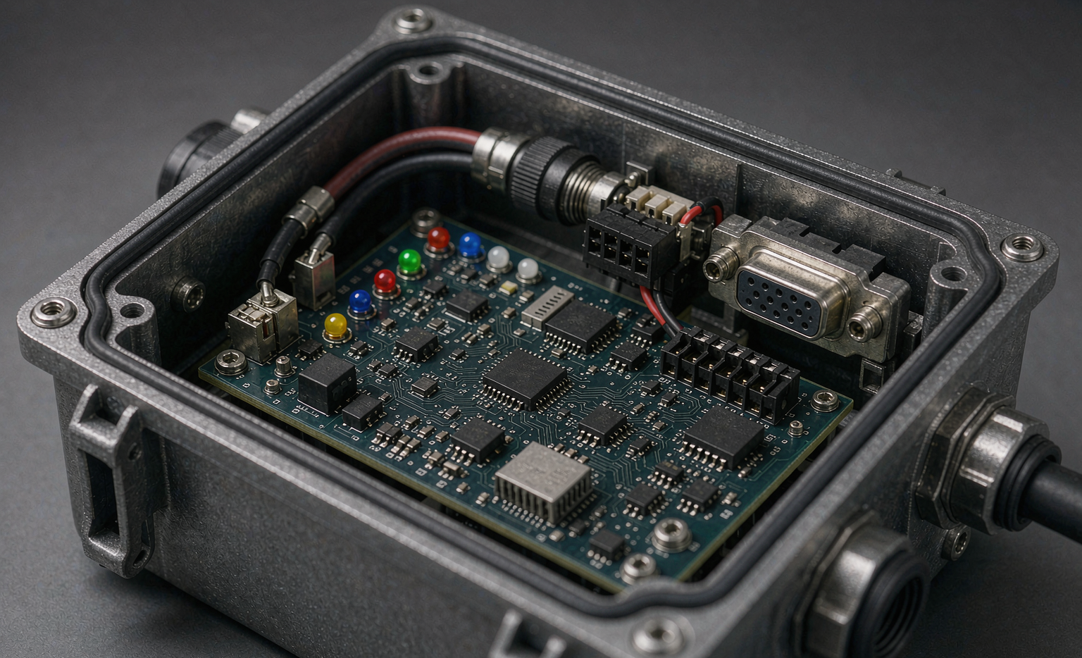
CAN bus gives the BMS a low latency channel to throttle current, request a voltage target, report cell temperatures, and abort the session on a fault. For a lithium battery charger this means the power stage can follow the pack instead of a fixed curve. The result is faster, cooler, and safer charging, and it is the difference between a consumer brick and a piece of industrial equipment a fleet can trust.
CAN Bus Fundamentals for Lithium Battery Systems
Most lithium battery chargers and BMS units speak CAN 2.0B at 250 kbps or 500 kbps on a twisted pair with a 120 ohm termination resistor at each physical end. The differential pair tolerates the electrical noise you find next to a power stage, which is exactly why CAN won the industrial bus wars over older standards for safety critical links. Messages use an 11 bit standard identifier for simple networks or a 29 bit extended identifier when you need a richer address space.
The BMS is normally the producer of telemetry frames and the consumer of control frames; the lithium battery charger is the reverse. A typical cycle runs at 10 Hz to 50 Hz, fast enough to catch a thermal event in its first seconds but light enough that an 8 byte frame budget is never exhausted. At Horizon Power we default to 500 kbps with 29 bit IDs for any pack above 1 kWh, because the extra address space pays for itself the moment a second charger or a gateway joins the bus.
The Charger to BMS Handshake Sequence
Integration starts with a handshake, not with current. When the lithium battery charger powers up it broadcasts a presence frame; the BMS answers with pack state, including cell count, nominal voltage, temperature spread, and allowed maximum charge current. Only after the charger confirms a valid response does it close its contactor and begin pre charge at a fraction of rated current.
From there the profile is a negotiation. The BMS streams a live current limit; the lithium battery charger ramps toward constant current, then toward constant voltage as cell voltage climbs. Termination is decided by the BMS, not the charger, the moment cell voltage reaches the target and charge current falls below the cutoff threshold. This single design rule, that the pack always terminates, is the one I defend hardest in reviews, because it keeps a firmware bug in the charger from ever overcharging a good pack.
CANopen, SAE J1939, or a Proprietary Frame Map
Three protocol families dominate. CANopen with the CiA 418 battery profile is common in European industrial and medical packs, and it gives you a documented object dictionary that accelerates integration. SAE J1939 is the heavyweight for trucks, buses, and off highway machines, with a rigid parameter group format that fleets already parse. A proprietary frame map is lighter and faster to ship, but it trades long term serviceability for short term speed.
For a lithium battery charger we usually recommend CANopen for stationary and material handling packs and J1939 for anything that shares a chassis with a vehicle. The mistake I see most is teams picking a proprietary map to save two weeks, then spending those two weeks again at every service call. If your custom battery solution will ship to more than one integrator, spend the effort on a standards based profile.
Real Time Telemetry and Safety Interlocks
The whole point of CAN bus is that safety lives in the loop. Every cycle the BMS publishes cell voltage, pack current, temperature at three points, and a fault word. The lithium battery charger subscribes and acts: it drops current when any cell crosses a temperature knee, holds at constant voltage when the spread widens, and opens its contactor the instant an over temperature or over voltage bit sets.
We also carry a watchdog. If the BMS stops transmitting for more than 250 milliseconds, the charger treats silence as a fault and shuts down rather than continuing on stale data. This fail safe posture is what lets a lithium battery pack pass UN38.3 and IEC 62133 reviews without a separate hard wired kill line, because the communication loss itself is a defined, tested, and safe state.
Integration Pitfalls I See in the Field
The first failure is termination. A CAN bus with only one 120 ohm resistor, or two at the wrong ends, rings and drops frames under load. The second is baud mismatch: a charger set to 250 kbps will not hear a BMS at 500 kbps, and both sides report a clean no fault because neither sees the other. The third is address collision, where two chargers share an identifier and the bus arbitration collapses into a broadcast storm.
The subtler ones are timing and trust. A lithium battery charger that retries a control frame too aggressively can mask a real BMS fault; one that trusts the first packet too long can miss a fast rising temperature. In our lab we log the full frame stream for every validation pack so we can replay a field failure instead of guessing at it. That log has settled more warranty arguments than any specification sheet.
Validation Before the Pack Ships
We do not ship a lithium battery charger integration on a bench confession. Every pack runs a scripted charge with injected faults: we kill the CAN link mid session and confirm the charger stops, we force a cell over temperature and confirm current folds to zero, and we pull the BMS telemetry and confirm the charger follows the limit frame by frame. Only when the bus behaves under stress do we close the build.
For customers building a custom battery solution, I recommend the same discipline. Ask for the frame map, ask for the fault table, and ask for a recorded charge that proves the lithium battery charger terminates on pack command. A supplier who cannot show you that log is asking you to trust a black box with a pack that can burn. Communication is not a feature you add at the end. It is the spine of the system.
Frequently Asked Questions
What is the difference between CANopen and SAE J1939 for chargers?
CANopen with the CiA 418 profile suits industrial and stationary lithium battery packs because it ships with a documented object dictionary, while SAE J1939 is built for vehicles and uses fixed parameter groups a fleet already understands. Pick CANopen for material handling and medical packs, J1939 for anything on a chassis.
What baud rate should a lithium battery charger CAN bus use?
Use 500 kbps for any pack above 1 kWh and 250 kbps for small or cost sensitive packs. Both run on a twisted pair with 120 ohm termination at each end, and the higher rate simply gives you more headroom when a gateway or second charger joins the network.
How does the BMS tell the charger to stop?
The BMS owns termination. When cell voltage reaches target and charge current falls below the cutoff, the BMS sets a fault or limit word on the bus and the lithium battery charger opens its contactor. The charger never decides to stop on its own, which keeps a charger firmware bug from overcharging the pack.
Can one CAN bus control multiple chargers?
Yes, with a 29 bit identifier space and unique addresses per node. The BMS broadcasts pack state while each lithium battery charger listens for its own control frames, so a single bus can manage a bank of chargers as long as the frame map prevents address collisions.
What happens if CAN bus communication fails during charging?
A well designed lithium battery charger treats silence as a fault. If the BMS stops transmitting for about 250 milliseconds, the charger shuts down rather than charging on stale data, giving you a safe tested state that satisfies UN38.3 and IEC 62133 expectations.
Do I need a terminating resistor on the charger side?
Only if the charger sits at a physical end of the bus. CAN needs exactly two 120 ohm resistors, one at each end, so if the lithium battery pack is one end and the charger is the other, the charger side must terminate. A missing or doubled resistor causes reflection and dropped frames under load.
Further Reading
References