
Battery Solution Deployment for Equipment
I have spent enough nights in equipment yards with a cold torque wrench in my hand to know a simple truth: a custom battery program rarely fails in the design office. It fails on the concrete, at 6 a.m., when a machine that started perfectly on the bench refuses to crank because nobody checked the voltage drop across a four-metre return cable. This guide is about that gap between a validated battery solution on paper and a machine that earns money every shift.
Over the last decade my team has deployed custom lithium packs into excavators, telehandlers, skid steers, mining loaders, airport ground support units, road rollers and factory AGVs. The applications differ wildly, but the deployment sequence that keeps them alive is remarkably consistent. Below is the sequence we actually use, including the numbers we hold ourselves to and the standards we audit against, because a custom battery solution is only as good as the hands that install it.
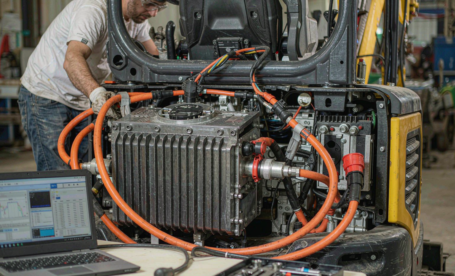
1. Why Deployment Deserves Its Own Budget Line
Engineering teams routinely spend months on cell selection, thermal modelling and BMS firmware, then allocate a single afternoon to installation. I have watched that decision cost more in warranty trips than the entire design budget. Deployment is the stage where the following variables finally become real:
- Mechanical reality. Frame twist, mounting flatness, washdown pressure, and vibration spectra that never match the datasheet.
- Electrical reality. Existing alternators, starter motors, hydraulic pumps, DC-DC converters and legacy wiring that was never designed for a low-impedance lithium source.
- Human reality. Operators who will plug in whatever charger is closest, technicians who will bypass an interlock to finish a shift, and a maintenance culture built around flooded lead-acid.
A pack built on an LFP chemistry will give you 3,000 to 4,000 cycles at 80% depth of discharge in the lab. In the field, that number collapses fast if the enclosure sits at 65 °C behind a hydraulic pump, or if the pack spends every night at 100% state of charge in a 40 °C container. Deployment is where you defend the cycle life you paid for.
2. Pre-Deployment Audit: Machine, Duty Cycle and Electrical Architecture
Before a single bracket is cut, we run a three-part audit. It takes two to three days per machine family and it is the highest-return work in the whole program.
2.1 Duty cycle instrumentation
We log the machine for one to two full working weeks with a current shunt and a temperature logger on the existing battery. What we are looking for is the true load profile: cranking transients, hydraulic peak currents, idle periods and overnight parasitic drain. On a 24 V diesel platform, cold cranking pulls 600 to 1,200 A for two to four seconds; on a 48 V mild-hybrid system with an electric swing drive, regenerative peaks can hit 400 to 600 A in both directions.
The audit tells us three things that no datasheet can: the C-rate envelope, the energy throughput per shift, and the thermal environment. A machine that consumes 8 kWh per eight-hour shift with 1,200 A cranking events needs a very different cell — high-power LFP or LTO, not a high-energy NCM cell optimised for range.
2.2 Electrical architecture review
Next we map everything attached to the DC bus. On legacy equipment this often means a 24 V or 48 V bus with a brushed alternator, an unregulated tap for lights, and an inverter hanging off the same terminals. Lithium changes the rules here in three ways:
- Charging profile. A lead-acid alternator curve will hold an LFP pack at a partial state of charge indefinitely, and the BMS will eventually disconnect on cell imbalance. We almost always specify a controlled DC-DC charger with an LFP profile: bulk 28.4 to 29.2 V on a 24 V nominal system, float 27.0 to 27.6 V.
- Regenerative absorption. A full lithium pack at low temperature cannot absorb a 600 A regen pulse. The BMS will open the contactor, and the machine loses its electric brake. Every deployment needs a defined regen clamp — a braking resistor, a hydraulic dump, or a charge-current derate tied to cell temperature.
- Fault current. A lithium pack has far lower internal resistance than lead-acid. Short-circuit currents that used to sag to 1,500 A can now exceed 8,000 A. Every fuse, contactor and cable in the existing harness has to be re-rated against the prospective fault current, not the nominal load.
2.3 Compliance baseline
We freeze the regulatory baseline early, because it constrains the battery pack design itself. For equipment work the usual list is:
- UN 38.3 (T1–T8) with a test summary available from the manufacturer — mandatory for transport since 1 January 2020.
- IEC 62619 for industrial secondary cells, including clause 7.2.2 charge temperature limits.
- IEC 62133-2 for portable sealed cells where the pack straddles portable and industrial definitions.
- IEC 62485 for installation safety — including the dielectric withstand test at 2U + 1,000 V AC for one minute.
- ISO 6469-3 for electrical safety on electrically propelled vehicles, notably the 100 Ω/V insulation monitoring threshold.
- IEC 60204-1 for electrical equipment of machines, which governs disconnecting means and protective bonding on the host machine.
- ISO 13849-1 / IEC 62061 where the battery contactor forms part of a safety function — we typically target PL d or SIL 2 for the emergency-disconnect path.
- IEC 60529 / ISO 20653 / IEC 62262 for ingress and impact: IP66, IP67 or IP69K depending on washdown practice, IK08 to IK10 for exposed enclosures.
- ISO 16750-3, SAE J2380 and ISO 12405-3 for mechanical and vibration qualification.
If the machine crosses a public road, add UN ECE R100 Rev.2 and ADR special provisions 376/377. If it ships by air, the pack must travel at no more than 30% state of charge under IATA DGR for UN3480. If it lands in the EU, the digital battery passport under Regulation (EU) 2023/1542 starts applying to industrial batteries above 2 kWh from 18 February 2027 — worth designing the data model for now rather than retrofitting it.
3. Mechanical Installation: Mounting, Sealing and Vibration Isolation
This is where field failures are born. A pack that survives the bench shaker can still crack a weld in three months if it is bolted to a twisting frame with no compliance.
3.1 Mounting and structural isolation
We mount the enclosure on a machined sub-frame rather than directly to the machine chassis, with elastomeric isolators selected to put the pack’s first resonant frequency above the dominant excitation band. For diesel equipment the excitation is typically 8 to 200 Hz (engine firing orders plus hydraulic ripple); we target a pack resonance above 45 Hz or below 8 Hz, never in between. Isolator durometer is chosen so that static deflection lands around 3 to 6 mm.
Mounting flatness matters more than people expect. On a welded frame, we shim to within 0.5 mm across the footprint before torquing, because a twisted enclosure transfers preload straight into the module stack and eventually cracks the busbar welds. Torque values on tinned copper lugs are not guesswork: M8 terminals typically land at 12 to 15 N·m, M10 at 25 to 30 N·m, and every critical fastener gets a torque-stripe witness mark plus a documented re-torque at 50 service hours.
3.2 Sealing, breathers and thermal path
An IP66 rating on a datasheet means nothing if the cable glands are installed by someone in a hurry. We use metal-bodied EMC glands with the correct clamping range, orient every connector downward or with a drip loop, and fit a GORE-style hydrophobic breather vent to equalise pressure without drawing in moisture. On washdown equipment, we specify IP69K and verify with an actual 80 °C, 80–100 bar spray test at commissioning, not just a visual check.
Thermally, the golden rule is simple: keep the pack out of the hot zone. Behind a hydraulic pump or next to an exhaust manifold, ambient can sit at 70 to 90 °C, and cell temperature is the single largest driver of calendar aging. Where relocation is impossible, we add a ducted fan or a liquid cold plate with a 2 to 3 kW capacity and hold cells below 45 °C under the worst-case duty cycle. Anything above 55 °C during charging should trigger a hard derate in the BMS solution firmware, and below 0 °C charging must be inhibited entirely, with a reduced-current band of 0.2 to 0.5 C between 0 and 15 °C.
4. Electrical Integration: Cabling, Protection and BMS Communication
4.1 Cable sizing and routing
We size the main DC loop for a 3% voltage drop and sense leads for 1%. On a 24 V system carrying 300 A over a 4 metre round trip, that means a minimum of 35 mm² of copper; push the run past 6 metres or the ambient past 50 °C and we go to 50 mm². Fine-strand, high-flex, 125 °C-rated cable is non-negotiable on vibrating machines, and every termination gets a closed-end tinned copper lug crimped with a calibrated hex die — never a hammer crimp.
Routing discipline is what keeps the system diagnosable: power and signal separated by at least 200 mm or crossed at 90°, sense leads twisted and routed independently of the power conductors, and the entire harness supported every 300 mm with cushioned clamps. On machines with an electric drive, we also keep the traction loop and the 24 V control loop physically segregated so a traction fault cannot darken the controller.
4.2 Protection and fault coordination
Every deployment gets a layered protection scheme, and we verify the coordination rather than assuming it:
- Contactor rated for the full load current with a DC breaking rating at the system voltage — never an AC rating. We specify a minimum of 1.5× nominal continuous current to handle regen and inrush.
- Fuse or DC circuit breaker placed within 150 to 200 mm of the battery positive terminal, sized at 125% of continuous load and 156% where the duty cycle is continuous, with I²t selectivity verified against the contactor and the BMS trip curve.
- Pre-charge circuit for any load with significant input capacitance. Without it, closing the contactor into an empty DC-link capacitor bank welds the contacts on the first cycle. We size the pre-charge resistor for a 3 to 5 RC time constant, typically two to five seconds.
- Insulation monitoring device set to 100 Ω/V per ISO 6469-3, with a warning at 500 Ω/V and a hard trip at 100 Ω/V on high-voltage platforms.
- Emergency disconnect wired into the machine’s safety chain where applicable, tested as part of the safety function to PL d or SIL 2 rather than treated as a convenience switch.
4.3 BMS communication and host integration
The BMS is not a black box; it is the machine’s new source of truth. We integrate over CAN 2.0B at 250 or 500 kbit/s using a documented DBC, exposing at minimum pack voltage, current, SoC, SoH, cell voltage min/max, cell temperature min/max, insulation resistance, contactor state and active fault codes. On telematics-equipped fleets, we map those signals onto the existing telematics payload so the service manager sees battery faults in the same dashboard as engine codes.
Two configuration details cause most early-life grief. First, the current sensor zero offset — we calibrate at true zero before installation, because a 1 A offset drifts SoC by several percent per week. Second, the contactor drive logic: the host controller must respect the BMS charge/discharge enable flags rather than simply commanding the contactor closed. Every bypass we have found in the field was installed by a technician trying to finish a shift.
The same engineering discipline applies to smaller platforms. When we commission a drone battery pack for a survey or inspection aircraft, we apply the identical pre-charge, connector-latching and insulation checks — just at 200 g instead of 200 kg.
5. Commissioning and Acceptance Testing on Site
Commissioning is a formal gate, not a handshake. Our on-site acceptance protocol runs about four hours per machine and produces a signed record:
- Visual and mechanical inspection. Torque marks present, isolators seated, glands torqued, no foreign objects, breather clear, labels legible.
- Insulation resistance. 500 V DC megger between the pack terminals and chassis. Accept only above 100 Ω/V; healthy new builds read in the tens of MΩ. Anything under 1 MΩ gets investigated before energising.
- Dielectric withstand. 2U + 1,000 V AC for 60 seconds per IEC 62485. On a 24 V system that is roughly 1,048 V AC, which surprises people who assume low voltage means low risk.
- Polarity and pre-charge verification. Confirm polarity at the load end, then time the pre-charge and record the inrush peak.
- BMS functional test. Inject each alarm and observe the correct response: over-voltage, under-voltage, over-current, over-temperature, insulation fault, communication loss. We do not accept “the faults are configured” as evidence.
- Capacity and DCR baseline. A full 0.2 C or 0.5 C capacity test to record actual amp-hour delivery, plus a DC internal resistance measurement at 25 °C. This baseline is the reference for every future warranty conversation; without it you have no way to prove degradation.
- Thermal survey under load. Run the machine through its real duty cycle for 30 to 60 minutes, then scan every termination with an IR camera. Our rule: a 20 K rise over ambient triggers investigation, 30 K triggers shutdown and rework. Terminations should sit within 5 to 10 K of each other.
- Contactor cycle test. Twenty open/close cycles under load, monitoring for voltage deviation at the load terminals.
We also record the resting cell-voltage spread after a 24-hour balance: up to 30 mV is healthy on a fresh pack, 50 mV is our alarm threshold, and anything beyond that on a new installation usually points to a bad sense connection rather than a bad cell.
6. Operator Training and Staged Fleet Rollout
The best installation in the world will be undone by an operator who pressure-washes the enclosure at close range or jump-starts the machine from a 24 V welder. Training is 60 minutes, hands-on, and covers exactly five things: what the state-of-charge display means, how and when to charge, what the warning lights mean, what to do when a fault appears, and what never to do (bypass interlocks, open the enclosure, use a non-approved charger).
Then we stage the rollout. Our standard pattern for a fleet conversion is:
- Pilot batch: 5 to 10 units across the hardest duty cycles, not the easiest, run for 500 service hours or three months.
- Design freeze review at the end of pilot — every fault, every cable chafe point, every thermal excursion feeds back into the battery pack design.
- Wave two: 20 to 25% of fleet, with a two-week observation window.
- Full deployment once the fault rate is under a defined threshold, typically fewer than one battery-attributable downtime event per 2,000 service hours.
Spare strategy gets decided before wave two, not after the first failure. We provision a spare pool of 3 to 5% of installed units, target a 4-hour mean time to repair on site, and hold a 24-hour replacement commitment from the factory. That last number matters more to an equipment manager than any cycle-life claim.
7. Documentation, Transport and Compliance Handover
The handover package for each deployment contains: the UN 38.3 test summary, the IEC 62619 / IEC 62133-2 test reports, the wiring schematic with wire numbers, the torque schedule, the commissioning record with DCR and capacity baselines, the BMS DBC file, the risk assessment, and the maintenance schedule. For cross-border fleets we also include the IATA DGR or ADR shipper’s declaration template and confirm the pack ships at 30% SoC or less under UN3480 for air freight.
One item that is easy to overlook: every pack above 100 Wh needs the watt-hour rating marked on the case, and industrial batteries above 2 kWh entering the EU will need a digital battery passport under Regulation (EU) 2023/1542 from February 2027. Capturing cell chemistry, manufacturing date, carbon footprint and recycled content at the point of deployment is far cheaper than reconstructing it later — something we learned the hard way on a 400-unit agricultural order.
8. Operations, Maintenance and End-of-Life
Once machines are working, deployment turns into a rhythm. Monthly: visual inspection of glands and isolators, and a review of the telematics fault log. Quarterly: torque spot-check on 10% of terminations, insulation resistance measurement, and an IR scan under full load. Annually: capacity verification against the commissioning baseline and a full balance cycle.
End-of-life criteria should be written into the contract before the first machine ships. Ours are: capacity below 80% of nameplate, DC internal resistance above 1.3× beginning-of-life, or a resting cell-voltage spread above 50 mV that cannot be resolved by balancing. Anything that fails those criteria comes off critical duty and either goes to a lower-demand application or into the recycling stream with the chemistry clearly documented — a detail waste handlers will increasingly demand evidence for.
I have seen equipment conversions deliver a 30 to 45% reduction in fuel use on hybrid platforms, an 8 to 12 dB noise reduction on night municipal work, and maintenance intervals that stretch from weekly to quarterly. I have also seen a fleet of thirty units sidelined for a month because nobody specified a pre-charge circuit. The difference was never the chemistry or the cells. It was the deployment discipline.
Frequently Asked Questions
How long does a typical equipment battery deployment take?
For a single machine family with an existing approved design, expect two to three days for the audit, one to two days for mechanical and electrical installation, and half a day for commissioning. A full fleet conversion of 50 units typically runs 8 to 14 weeks including the pilot phase, because the pilot and the design freeze review are worth the calendar time.
Can a custom lithium pack replace lead-acid without changing the machine’s charging system?
Almost never. Lead-acid alternator profiles hold a lithium pack at partial state of charge and eventually trip the BMS on cell imbalance. At minimum you need a controlled DC-DC charger with an LFP profile — bulk 28.4 to 29.2 V on a 24 V nominal system, float 27.0 to 27.6 V — together with a temperature-based charge inhibit below 0 °C.
What certification should I demand from a battery supplier before deployment?
UN 38.3 test summary (mandatory for transport since January 2020), IEC 62619 for industrial cells, IEC 62133-2 where the pack is portable, and IEC 62485 evidence for installation practice. For road machines add UN ECE R100 Rev.2 and ADR special provisions 376/377; for machines where the battery contactor participates in a safety function, ask for ISO 13849-1 PL d or IEC 62061 SIL 2 documentation.
Why does my pack’s contactor weld or fail early?
In approximately eight out of ten cases we investigate, the root cause is an absent or undersized pre-charge circuit. Closing a contactor into an uncharged DC-link capacitor bank produces an inrush spike that welds the contacts or erodes them within a few hundred cycles. Size the pre-charge resistor for a 3 to 5 RC time constant — two to five seconds is typical — and verify the inrush peak during commissioning.
How do I size the DC cabling on a 24 V equipment installation?
Design for a 3% voltage drop in the main power loop and 1% in sense leads. At 24 V and 300 A over a 4 metre round trip that means at least 35 mm² of fine-strand copper rated to 125 °C; move to 50 mm² if the run exceeds 6 metres or ambient exceeds 50 °C. Terminate with hex-crimped tinned copper lugs, and re-torque at 50 service hours.
What temperature limits should the BMS enforce on equipment packs?
Charging must be inhibited below 0 °C, with a reduced-current band of 0.2 to 0.5 C between 0 and 15 °C. Charging above 45 °C should derate, and above 55 °C should stop. Discharge is generally safe from −20 °C to 60 °C, though available capacity at −20 °C drops to roughly 70–80% of nameplate for LFP and 88–92% for sodium-ion chemistries.
How should we plan the rollout across a mixed fleet?
Start with 5 to 10 units on the hardest duty cycles, run 500 service hours or three months, hold a design freeze review, then release wave two at 20 to 25% of the fleet. Full deployment should follow only when the battery-attributable downtime rate drops below one event per 2,000 service hours. Provision a 3 to 5% spare pool before wave two, not after the first failure.
When should an equipment battery be retired?
Use three objective criteria agreed in the contract: capacity below 80% of nameplate, DC internal resistance above 1.3× beginning-of-life, or a resting cell-voltage spread above 50 mV that balancing cannot resolve. Measuring against a commissioning-day baseline is the only way to make those criteria enforceable.





