Lithium Battery Safety for Solar Kits
I have spent more than a decade designing and qualifying lithium battery packs for OEM customers, and the category that generates the most field complaints is not the drone world or the EV world — it is the humble off-grid solar kit. A solar kit looks like the simplest product in the catalogue: a panel, a controller, a battery, some cables. In practice it is the place where the widest gap exists between what the buyer assumes and what the hardware actually does. When a pack fails in a solar kit, it rarely fails because the cells were bad. It fails because the system around the cells was never engineered as a system.
This guide is written for procurement teams, product managers and integrators who specify, private-label or deploy solar kits with a lithium battery pack inside. My focus is lithium battery safety for solar kits specifically: the failure modes that are unique to small, user-assembled, intermittently charged, outdoor-installed systems, and the design and qualification decisions that prevent them.
Why Solar Kit Battery Safety Is Not the Same Problem as Stationary Storage
Engineers who come from grid-tied or commercial storage projects tend to apply the same safety playbook to solar kits and get surprised. A residential ESS is installed once by a licensed electrician, lives in a controlled environment, is protected by a listed inverter, and is commissioned with instrumentation. A solar kit is carried by an end user, assembled in under an hour, mounted on a balcony, a boat, a shed wall or the roof of a hut, and then — critically — left unattended for months.
That difference drives four distinct risk multipliers.
- User-assembled connections. Ring terminals, MC4 connectors and Anderson plugs are made by hand. Every hand-made joint is a potential resistance point, and a 2 mΩ increase at 60 A is 7.2 W of local heat — enough to discolour insulation over a season.
- Intermittent, partial-state-of-charge operation. Solar kits live between 30% and 90% SoC for weeks. This is excellent for cycle life but it starves the balancing function: passive balancers in most BMS designs only bleed at the top of charge. Without a periodic full charge, cell drift accumulates silently until one cell trips on overvoltage.
- Unknown charge sources. Kits get paired with third-party panels, generators, car alternators and cheap PWM controllers that were never validated against the pack’s charge profile.
- Environmental extremes with no service interval. A pack mounted behind glass on a south-facing wall can sit at 70 °C internal temperature in summer and be asked to charge at −5 °C in winter. Both ends of that range are dangerous for different reasons.
When we take on a solar kit programme, we treat it as a custom battery solution rather than a catalogue item, precisely because the boundary conditions are set by the end user and not by us. That changes how we specify the BMS, the enclosure and the documentation.
Chemistry: Why LFP Is the Default Answer for Solar Kits
Almost every credible solar kit on the market today uses LiFePO4 (LFP), and the safety case is straightforward. The olivine phosphate cathode has a strong P–O covalent bond that resists oxygen release, so the onset of exothermic decomposition sits roughly 70–100 °C higher than in layered-oxide NCM cells. In accelerating rate calorimetry (ARC) work we run on 32700-format cells, LFP typically shows self-heating onset (T1) around 180–210 °C versus 120–150 °C for NCM811, and a thermal runaway onset (T2) above 250 °C versus 180–200 °C. Peak self-heating rates differ by an order of magnitude.
For solar kits there are three additional reasons beyond the thermal numbers:
- Voltage compatibility. A 4S LFP pack (12.8 V nominal, 14.4–14.6 V absorption) drops into electrical systems designed for 12 V lead-acid, including most pumps, lights and inverters, without exceeding their input limits. A 3S NMC pack (11.1 V nominal) does not.
- Cycle life under partial cycling. LFP routinely delivers 3000–4000 cycles to 80% capacity at 80% depth of discharge and 25 °C. Field data from kits deployed in 2019 are still returning 88–92% of nameplate capacity.
- Tolerance of abuse margins. If a cheap controller overshoots absorption voltage by 0.3 V, LFP tolerates it (within limits); NCM does not forgive the same error.
The trade-off is energy density — roughly 90–130 Wh/kg at cell level versus 180–250 Wh/kg for NCM — which matters little for a stationary or semi-portable kit, and cold-temperature charging, which matters a great deal and which we address next.
Charge Control: The Single Biggest Safety Lever
If I could only review one subsystem in a solar kit design, it would be the charge path. In my incident reviews, roughly 60% of pack failures trace back to charge control rather than to the cells.
MPPT, PWM and the voltage profile problem
A PWM controller is a switch: it connects the panel to the battery and lets the panel’s current collapse toward the battery voltage. It has no concept of constant-current/constant-voltage (CC-CV) charging. A 12 V “100 W” panel with a Vmp of 18 V feeding a 12.8 V LFP pack through PWM will push current whenever the panel voltage exceeds pack voltage plus the diode drop — including at 15 V or more if the controller lacks a proper regulation setpoint. Many low-cost PWM units have only a crude overvoltage disconnect at 15.5–16 V, which is far above the 14.6 V that LFP should ever see in normal service.
MPPT controllers convert the panel’s maximum-power-point voltage down to the battery voltage with a buck stage and implement a real CC-CV curve. The difference in absorption accuracy is typically ±50 mV for a decent MPPT versus ±300–500 mV for PWM. For lithium, that accuracy is the difference between a pack that balances and a pack that drifts.
Design rules I apply:
- Absorption (CV) voltage: 14.2–14.6 V for a 4S LFP pack at 25 °C; 28.4–29.2 V for 8S (24 V); 56.8–58.4 V for 16S (48 V).
- Float: 13.5–13.6 V. Holding LFP at absorption indefinitely is unnecessary and accelerates calendar ageing; a genuine float stage or a charge-termination algorithm is preferred.
- Tail-current termination: 0.02C–0.05C. Without termination, the pack sits at the CV voltage trickling current, which is where passive balancing finally works but also where plating risk rises if the cells are cold.
- Temperature compensation: disable it for lithium. Lead-acid chargers apply −18 to −30 mV/°C per 12 V block to raise voltage in cold weather. Applied to lithium, that compensation pushes the pack into overvoltage at low temperature and into undercharge at high temperature. This single legacy feature has caused more lithium incidents than any other charger behaviour.
Low-temperature charging and lithium plating
Charging a graphite-anode lithium cell below roughly 0 °C drives metallic lithium plating on the anode surface instead of intercalation. Plated lithium is partly irreversible — it consumes cyclable lithium, raising internal resistance — and partly dangerous, because dendrites can penetrate the separator and create an internal short that appears weeks later as a self-heating event with no external trigger.
Every solar kit we build carries a charge inhibit based on the coldest cell thermistor, with hysteresis:
- Charge inhibit below 0 °C (some chemistries and power cells tolerate −10 °C at ≤0.05C; I only permit that with cell-maker test data in hand).
- Resume charging at +5 °C to avoid chatter at the threshold.
- Derated current between 0 °C and 15 °C — typically 0.2C below 5 °C, 0.5C below 15 °C.
- Discharge cut-off at −20 °C, with a −10 °C power-derate step.
- An internal heating path — a resistive film or a self-heating function — for kits sold into alpine, Nordic or Canadian markets. I specify 30–60 W of pad power for a 100 Ah enclosure, controlled by the BMS and supplied from the panel so it does not drain the pack.
IEC 62619 clause 7.2.2 requires that charging be prevented outside the manufacturer’s declared temperature limits; this is not optional in any market that references the standard.
What the BMS must do — and what it cannot do
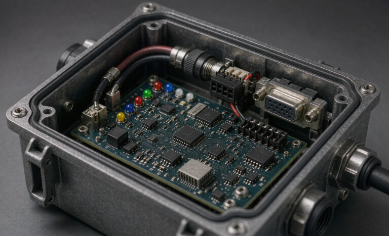
A BMS solution for a solar kit is not just a protection board. It is the last line of defence against everything the charge controller does wrong. Minimum requirements I hold suppliers to:
- Cell overvoltage protection at 3.65 V ±25 mV for LFP, with recovery hysteresis of 100–150 mV.
- Cell undervoltage protection at 2.5 V (2.0–2.3 V for deeper chemistries with cell-maker approval), with low-SoC load disconnect at 2.8–2.9 V to prevent a kit that sits idle for a month from bricking itself.
- Charge overcurrent at 1.1–1.2× the controller’s rated output; discharge overcurrent at 1.5–2.0× rated continuous for 10–30 s, and a short-circuit trip within 100–500 µs.
- Charge MOSFET body-diode blocking or back-to-back MOSFETs so that a reversed or over-voltage source cannot force current into the pack when the FETs are open.
- Passive balancing at 50–100 mA with top-of-charge balancing only, plus a documented “equalisation charge” procedure — one full absorption every 30 days — in the user manual.
- Secondary protection that is independent of firmware: an analogue comparator chain or a thermal fuse / PTC that opens the loop if the MCU hangs.
One thing the BMS cannot do is compensate for a controller that applies 15.5 V. Overvoltage protection will disconnect the pack, but repeated tripping under a hot panel on a cold morning — when panel Voc rises 0.3–0.4%/°C below 25 °C — creates exactly the chattering failure mode that wears out MOSFETs. A 20-cell-panel string with Voc of 45 V at 25 °C can reach 50 V at −20 °C, which is why controller input voltage rating must be checked at the record low temperature, not at STC.
Wiring, Fusing and Thermal Realities
The second-largest failure cluster in solar kits is the DC harness. Sizing rules I use:
- Total loop voltage drop ≤3% at rated continuous current (≤1% for the BMS sense harness).
- Conductor cross-section from the ampacity table for the installed environment — a 4 m round trip at 100 A in 90 °C-rated copper needs 25 mm², not the 16 mm² that “looks about right”.
- Overcurrent device sized at 125% of continuous current, applied continuously (NEC 210.20(A)); where the load is continuous for more than three hours, we often go to 156%.
- Break the fault loop properly: a Class T or NH/gG DC fuse within 150–200 mm of the battery positive terminal, rated for the DC voltage of the string (never an AC-rated device), plus a DC breaker as the service disconnect.
- Crimp, then pull-test (a 6 mm² terminal should survive 300 N), then torque to 70–75% of the fastener proof load with a calibrated driver, paint-mark, and re-torque after the first thermal cycle.
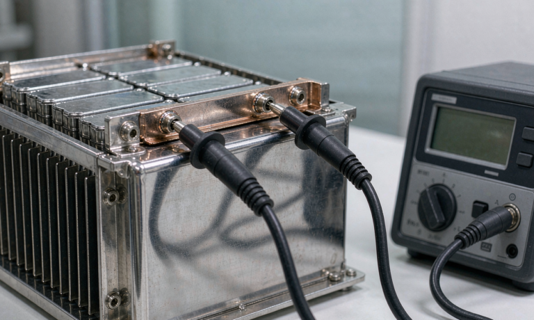
On the thermal side, the numbers that matter are simple. Internal resistance rise is the earliest detectable degradation signal: a healthy 100 Ah LFP prismatic cell measures 0.5–1.0 mΩ; when DCR reaches 1.3× beginning-of-life, the cell is at end of qualification. At pack level, an infrared scan after 30 minutes at rated load should show no terminal or busbar running more than 20 K above the coolest point in the same current path — a ΔT of 20 K is my “stop and investigate” threshold, and 30 K is a hard stop.
Kits are frequently installed in sealed enclosures, in direct sun, or inside vehicle compartments. Derate accordingly: a pack rated for 60 °C ambient loses roughly 20–30% of its calendar life for every 10 °C sustained increase above 25 °C, following Arrhenius behaviour with an effective activation energy of roughly 60–80 kJ/mol for the dominant SEI-growth mechanism. Ventilation, a reflective cover, and a sun-shaded mounting location are free capacity.
Environmental Protection: Enclosure, Ingress and Condensation
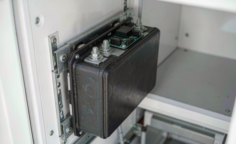
For outdoor kits I specify a minimum of IP54 for wall-mounted enclosures under eaves and IP65 for exposed locations, tested to IEC 60529. But the IP rating is not the failure mode that actually kills these packs — condensation is. A sealed enclosure that breathes through a cable gland will pull in humid night air and condense on the coldest surface, which is usually the BMS PCB. The fix is a vapour-permeable, liquid-tight vent (Gore-type membrane, typically 0.2–1.0 L/min at 7 kPa) mounted low on the enclosure, plus conformal coating (IPC-CC-830B qualified, 25–75 µm) on the BMS and a drainage path that does not pool beneath the cells.
Additional environmental checks:
- UV resistance of any exposed polymer — PC/ABS blends chalk and crack in 2–3 years; ASA or UV-stabilised polycarbonate is worth the cost.
- Salt-fog exposure for marine kits: 480–1000 h to IEC 60068-2-52 severity 5–6, with stainless 316 fasteners and tinned copper conductors.
- Vibration and shock for kits that travel in vehicles: IEC 60068-2-64 random vibration (typically 5–10 Grms over 10–500 Hz) and IEC 60068-2-27 half-sine shock (15–30 G, 6–11 ms), with cell bracing that preloads the stack at 5–15 kPa.
- Galvanic isolation — never mate aluminium enclosure hardware directly to copper busbars without a plated transition or a compatible interface.
Certification and Transport: What to Demand from a Supplier
Any credible lithium battery manufacturer supplying solar kits should hand you a documentation package without being asked twice. My checklist:
- UN 38.3 test summary covering T1–T8 (altitude, thermal, vibration, shock, external short, impact/crush, overcharge, forced discharge), issued for the specific cell and for the assembled pack where the pack exceeds the cell-level exemptions.
- IEC 62133-2 for the cell and pack, or IEC 62619 where the kit is used in stationary industrial applications. IEC 62619 covers the propagation and thermal considerations that IEC 62133 does not.
- UL 1973 for North American stationary and light electric applications; UL 9540 / UL 9540A only become relevant once the kit is integrated into a fixed ESS above the relevant capacity thresholds.
- IEC 60529 IP test report and, where claimed, IEC 62262 IK rating for the enclosure.
- IEC 62485 (or IEC 62485-2 for lithium) installation-safety guidance, including insulation resistance testing at 2U + 1000 V DC for one minute and a minimum 100 Ω/V insulation monitoring threshold.
- An MSDS/SDS and a valid UN38.3 test summary for air freight, plus confirmation of state-of-charge: IATA DGR requires lithium-ion cells and batteries shipped alone (UN3480) to be at no more than 30% SoC.
- Marking: rated capacity in Wh, nominal voltage, polarity, chemistry, and — for the EU market — preparation for the EU 2023/1542 battery passport obligation that phases in from 2027.
Installation codes vary by jurisdiction; for North America the relevant anchors are NEC Article 690 (solar PV), Article 705 (interconnected sources) and — for systems installed under the 2020 code cycle — Article 706, which was relocated into Article 480 in the 2023 cycle. Kits intended for indoor installation in dwellings also interact with NFPA 855 once aggregate capacity crosses 20 kWh, which is larger than most kits but not larger than a banked installation of them.
Commissioning Checklist and Failure Modes I Have Actually Seen
The commissioning step is where a good design is either confirmed or wasted. A 20-minute procedure catches nearly everything:
- Insulation resistance: 500 V DC (or 2U + 1000 V for the pack, per IEC 62485) between each polarity and the enclosure; accept above the 100 Ω/V floor, expect tens of MΩ on a healthy new unit.
- Verify polarity at the terminals with a meter, then verify again at the controller end before the final connection.
- Confirm the controller profile matches the chemistry — LFP profile, temperature compensation off, absorption and float within the ranges above.
- Torque audit: 100% of power terminals, paint-marked, with a documented value.
- Functional test of every BMS alarm: inject overvoltage, undervoltage, overcurrent and over-temperature faults by simulation where the BMS supports it, and confirm the contactor or MOSFET opens and the app reports the event.
- Load test at rated current for 30 minutes, then infrared scan.
- Record the as-shipped internal resistance and static cell spread as the baseline for all future service decisions.
Real failures from my incident files, all of them preventable:
- Reversed Anderson connector. A user crimped the red and black in the wrong order; the controller’s input capacitors discharged through the pack before any protection reacted. Fix: mechanically keyed, non-reversible connectors and a polarity-protection MOSFET on the charge input.
- Lead-acid charger left in circuit. The user replaced a 12 V AGM with LFP and kept the old charger with its 14.8 V equalisation and −24 mV/°C compensation. The pack tripped overvoltage every cold morning for three weeks, then one cell vented. Fix: chemistry-selectable chargers and a prominent label inside the enclosure.
- Undersized harness in a hot enclosure. 10 mm² cable on a 100 A inverter surge, inside a black box on a tin roof at 65 °C ambient. The insulation softened, the terminal relaxed, resistance rose, and the terminal melted. Fix: correct ampacity at the actual ambient, plus a 90 °C-rated silicone or XLPE conductor.
- Never reaching absorption. An undersized panel in a Scottish winter never brought the pack above 13.8 V, so balancing never ran and cell drift reached 180 mV in 14 months. Fix: monthly equalisation charge and a BMS that balances down to 3.40 V rather than only above 3.45 V.
- Condensation on the BMS. Sealed IP67 box, no vent, mounted where it saw daily thermal cycling. Water pooled on the PCB and corroded the current-shunt traces, and the BMS began misreading current by 30%. Fix: a drain-vent and conformal coating.
Service Life, Monitoring and Retirement Criteria
Solar kits are frequently deployed where nobody will service them, so the retirement criteria need to be remotely observable. I specify telemetry of pack voltage, current, the two extreme cell temperatures, per-cell voltages and accumulated amp-hours, and I define the following end-of-qualification triggers:
- Discharge capacity below 80% of nameplate at 0.2C and 25 °C.
- Pack DCR above 1.3× beginning-of-life at the same temperature and SoC.
- Static cell-voltage spread exceeding 50 mV after a full equalisation charge and 24 h rest.
- Any cell showing a self-discharge rate above 3% per month, or any enclosure deformation, odour, or electrolyte residue.
- Sustained operation above the declared temperature limits — once a pack has been cooked, I treat it as a candidate for replacement regardless of measured capacity, because the SEI damage is progressive.
With those rules applied, a well-designed LFP solar kit should deliver 8–12 years in temperate climates and 5–8 years in hot or continuously-cycled duty. The difference between the two ends of that range is almost never the cell — it is the charge profile, the harness and the enclosure.
Frequently Asked Questions
Can I use my existing lead-acid solar charge controller with a lithium battery pack?
Only if it has a selectable lithium profile or a user-defined profile with adjustable absorption, float and temperature compensation. A fixed lead-acid controller with equalisation mode and −18 to −30 mV/°C temperature compensation is not safe for lithium: the compensation raises voltage as temperature falls, which combined with cold cells is exactly the plating-plus-overvoltage combination that causes incidents. If your controller cannot be set to 14.2–14.6 V absorption, 13.5–13.6 V float and zero temperature compensation, replace it.
Is it safe to charge a solar kit lithium battery below freezing?
Not without protection. Below roughly 0 °C, lithium plates onto the graphite anode instead of intercalating, permanently losing capacity and creating dendrite-driven internal-short risk. The pack must have a charge inhibit driven by cell-temperature sensing, with a resume threshold around +5 °C and a derated current between 0 °C and 15 °C. Kits sold into cold climates should include a BMS-controlled internal heater supplied from the panel.
What size fuse or breaker do I need between the battery and the inverter?
Size the overcurrent device at 125% of the maximum continuous current, rounded up to the next standard rating, and confirm that the conductor ampacity exceeds the device rating after applying ambient-temperature and bundling derates. A 1000 W inverter on a 12.8 V pack draws roughly 85 A continuous, so 85 × 1.25 = 106 A, which means a 125 A DC-rated device on cable rated above 125 A at the installed ambient — typically 35 mm² for short runs. The device must be DC-rated at the system voltage and located within 150–200 mm of the battery positive terminal.
Why does my kit never seem to balance its cells?
Most passive balancers only bleed current when the highest cell is above roughly 3.45 V, which only happens near the top of charge. If the panel is undersized, the season is poor, or the load runs overnight, the pack may never reach absorption and balancing never activates. Specify a BMS that balances from 3.40 V, and schedule one full equalisation charge — absorption voltage held until tail current drops below 0.05C — at least every 30 days.
Do I need UL 9540A testing for a portable solar kit?
No. UL 9540 and UL 9540A apply to energy storage systems installed as fixed equipment and are driven by capacity thresholds in NFPA 855 and local amendments. A standalone portable or plug-and-play kit falls under IEC 62133-2, IEC 62619 and UL 1973, with UN 38.3 for transport. The 9540A question only arises when multiple kits are banked into a fixed installation — at which point the installer must obtain thermal-propagation data for the assembled configuration.
How often should a solar kit battery be inspected?
For a user-installed kit, twice a year: a visual inspection of the enclosure and connectors, an infrared check of terminals under load, and a full equalisation charge with a logged capacity test. For commercial deployments, add quarterly telemetry review of cell spread, DCR trend and temperature excursions. Anything showing more than 50 mV static spread after equalisation, or DCR above 1.3× beginning-of-life, should be scheduled for replacement rather than left in service.
Can I expand my kit by adding a second battery in parallel later?
Only with packs of the same chemistry, capacity, age, internal resistance and SoC. Paralleling a fresh pack with a three-year-old one circulates current between them as the stronger pack carries the load, and the resulting imbalance can exceed the BMS design limits. I specify a maximum of 0.2 V difference and 20% DCR difference between paralleled strings, with each string individually fused, and a pre-charge step to equalise voltages before closing the paralleling contactor.
What should I look for when choosing a custom battery solution supplier for solar kits?
Ask for the cell-maker’s UN 38.3 test summary and the pack-level IEC 62133-2 or IEC 62619 certificate, the IP test report to IEC 60529, the BMS functional-safety documentation including independent secondary protection, and the low-temperature charge-inhibit test data. Then ask two process questions: how do they verify crimp quality on every harness, and what is their torque-audit method. A supplier who cannot answer both is selling a commodity pack, not an engineered custom battery solution.