
Battery Solution Deployment for Robotics: An Engineer’s
Why a “battery solution deployment robotics” rollout is its own engineering discipline
I have spent the last nine years watching robotics fleets go from a novelty on the loading dock to the workhorse of warehouses, hospitals, and semiconductor fabs. The cell that quietly decides whether that fleet makes money or burns it is the lithium battery pack, and a “battery solution deployment robotics” project is the moment that cell meets the real world. A pilot run of three autonomous mobile robots (AMRs) can be deployed with almost any off-the-shelf pack and look fine. A fleet of two hundred automated guided vehicles (AGVs) running three shifts is an entirely different animal. I have seen well-funded automation programs stall because the team treated battery deployment like a plug-and-play accessory instead of the systems-engineering work it actually is.
This guide is the playbook I wish I had been handed on my first fleet deployment. It is written for the senior engineer or robotics program manager who has been asked to take a working prototype and turn it into a 200-unit production fleet, with real uptime targets, real safety auditors, and a CFO who wants payback in two years. We will move through the seven steps I now run on every custom battery solution deployment: scope the duty cycle, choose chemistry and form factor, plan the swap or charge strategy, engineer the charging bay, qualify the cells and pack, commission the fleet, and put a service plan in place. I will share the failure modes I have actually seen, the test data I actually trust, and the standards (UN38.3, IEC 62133-2, IEC 62619, UL 1973) I insist on before a single pack leaves my dock.
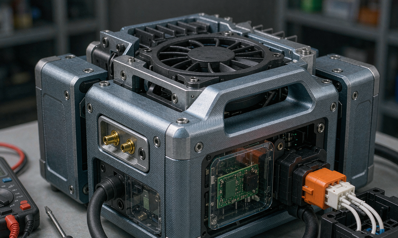
Step 1 — Lock the duty cycle before you spec a single cell
The first mistake on a robotics battery deployment is letting the integrator’s marketing brochure set the duty cycle. Real duty comes from the four numbers you measure on the actual route, not the ones printed in the proposal:
- Daily energy throughput (kWh) — the sum of every lift, drive, and idle load over 24 hours. I walk the route with a clamp meter and a notebook for one full shift before I quote anything.
- Peak continuous power (kW) — the worst-case draw during acceleration or lifting, not the average. An AGV that pulls 1.5 kW average can pull 8 kW peak at a docking turn, and that peak sets the C-rate you must design for.
- State of Charge (SoC) window — most fleet operators are happy cycling between 20% and 80%, but some ask for 10-90% to chase longer runtime. That single decision can cut cycle life by 40%.
- Environmental envelope — minimum and maximum ambient temperature, humidity, dust class (ISO 14644-1 for cleanrooms), and any vibration or shock loads from ramps and lifts.
Write these four numbers down and refuse to quote a lithium battery pack until they are signed off. Every decision downstream — chemistry, capacity, BMS topology, charging rate — flows from this single page. If your integrator cannot give you those numbers in writing, your battery solution deployment is being designed on a hope and a prayer.
Step 2 — Choose the chemistry and form factor that survives the route
For most AMR and AGV fleets I now specify lithium iron phosphate (LFP, LiFePO4) prismatic cells, and only deviate when a customer has a hard weight or volume constraint that forces nickel manganese cobalt (NMC) chemistry. The trade-off is straightforward:
LFP (LiFePO4) — the default for indoor fleets
- Nominal cell voltage 3.2 V, typical pack string 25.6 V (8S) for 24 V systems or 51.2 V (16S) for 48 V systems.
- Energy density 120-170 Wh/kg, which is fine for any AMR under 500 kg total mass.
- Thermal runaway onset around 270°C, versus 200-210°C for NMC, which is the difference between a contained cell event and a propagating pack fire.
- Cycle life at 80% depth of discharge (DoD), 25°C, 0.5C charge/discharge: 3,000 to 6,000 cycles, comfortably an 8-10 year fleet life.
- Calendar loss at 35°C and 100% SoC: 3-4% per year. Drop the storage SoC to 50% and you are below 1% per year.
NMC (LiNixMnyCozO2) — only when weight is the constraint
NMC buys you 180-250 Wh/kg, which matters for outdoor drones and last-mile delivery robots, but it cuts cycle life to 1,500-2,500 cycles and demands a much more sophisticated thermal envelope. I will not deploy NMC in a fleet that sits at 100% SoC on a charger for any meaningful fraction of the day; calendar loss at high SoC is brutal, and a thermal runaway event will take the whole robot with it.
Form factor — prismatic, cylindrical, or pouch
For a custom battery solution deployment robotics project, I default to prismatic cells in a welded aluminium housing. Prismatic cells are mechanically robust, easier to laser-weld into busbars, and tolerate the small cell-to-cell capacity variance (3-5%) that comes with every lot. Cylindrical 21700 cells (the Tesla format) are excellent for hot-swap packs because they cool evenly, but they require a more complex mechanical assembly. Pouch cells are only worth the weight saving when the robot has a tightly constrained battery bay, and they demand a rigid compressive frame to prevent swelling.
Step 3 — Design the swap or opportunity-charge strategy
This is where most fleet programs win or lose. You have three credible options for keeping a fleet running:
Option A — Opportunity charging at the work station
The robot pulls into a charging dock for 60-120 seconds between tasks. This works beautifully for low-duty AMR fleets (under 8 hours of driving per day) but requires careful fleet-management software to prevent a traffic jam at the dock. I size the charger at 1C continuous so a 100 Ah pack regains about 30% SoC in 10 minutes.
Option B — Battery hot-swap
The robot pulls into a swap station, a fresh lithium battery pack is automatically loaded, and the depleted pack goes to a slow charger. This is the only viable strategy for 24/7 fleets, but it requires the swap station to be safety-rated (an enclosure that contains a thermal event during the swap), and it doubles your battery count per robot because one pack is always charging. My rule: if your duty cycle exceeds 18 hours per day per robot, you are buying a swap system, not an opportunity-charge system.
Option C — Tethered or floor-induction charging
Floor-mounted induction pads or overhead conductive rails let the robot charge without a deliberate docking maneuver. Induction is elegant but inefficient (88-92% end-to-end versus 96% for conductive) and the pads are expensive to retrofit into an existing concrete floor. I usually steer customers away from induction unless the robot absolutely cannot have a protruding contact.
Step 4 — Engineer the charging bay like a piece of industrial equipment
A charging bay is not a wall box. For a fleet of more than ten robots, it is a piece of industrial machinery and must be engineered accordingly. The four things I always specify:
- Adequate ventilation and thermal headroom — every charger is rated for a 40°C ambient, but in a closed dock with ten chargers running the temperature can climb to 55°C. I derate chargers to 70% of nameplate when the bay is not actively cooled.
- Ground fault and arc-fault protection — a DC arc fault on a 48 V pack can weld a contact closed. I require DC-rated RCDs (Type B, 30 mA) on every charger and a series arc-fault detector that latches the contactor open on the first anomaly.
- Mechanical alignment tolerance under 2 mm — spring-loaded contacts work, but only if they engage cleanly. A misaligned dock that forces the robot to retry the docking maneuver will burn the contact plating in weeks.
- Network and protocol openness — every charger must expose Modbus TCP or CANopen registers for voltage, current, SoC, and fault codes at 1 Hz. If the charger’s protocol is proprietary, walk away. Locked-in chargers are the single most expensive mistake in a long-term battery solution deployment robotics program.
Step 5 — Qualify the cells, pack, and charger as a system
Cell-level test reports from the manufacturer are not enough. I run a four-stage qualification on every new lithium battery pack before it sees a robot:
- Cell grading at receipt — every cell is charged to 50% SoC, rested for one hour, and graded on capacity and DCIR. I reject any lot where the worst cell is more than 2% off the best cell on capacity or more than 5% on DCIR. A 3% capacity spread in a lot is normal; a 6% spread is a forecast of pack-level balancing failures in year two.
- Pack-level DCIR baseline — at 25°C, 50% SoC, a 0.5C 10-second discharge pulse gives me the pack DCIR. I record this number and compare it to the DCIR of the same pack after 100, 500, and 1,000 cycles. A DCIR increase of more than 30% over 1,000 cycles is the leading indicator of a failing pack.
- BMS open-protocol test — I pull the BMS register map and confirm cell voltage, cell temperature, pack SoC, pack state of health (SoH), and at least one 16-bit status word are exposed at 1 Hz. A BMS that hides SoH behind a vendor portal is a BMS that will fail your audit in year three.
- Standards stack before shipment — UN38.3 for transport (mandatory), IEC 62133-2 for portable cells, IEC 62619 for industrial lithium batteries, UL 1973 for stationary and motive battery systems, and, for any pack larger than 20 kWh, UL 9540A for thermal runaway propagation. These are not optional, and a manufacturer that cannot show you the test summaries in writing is not the right manufacturer.
Step 6 — Commission the fleet one robot at a time, then ramp
The temptation on deployment day is to bring all 200 robots online at once. Resist it. I commission in four passes:
- Single-robot shadow run — the first robot runs the full route with a safety observer and a data logger, while the fleet management software is in “training mode”. This pass catches mechanical misalignments and BMS fault thresholds.
- Five-robot shadow run — the next pass exercises traffic management, charging-bay queuing, and battery hot-swap reliability if applicable. I instrument every contactor close event.
- Twenty-robot controlled ramp — full fleet-management software, but with a human dispatcher ready to intervene. I run this for at least 72 hours before declaring the deployment stable.
- Full fleet rollout — staggered over one to two weeks, with daily morning stand-ups to triage the previous 24 hours of faults. The first 500 hours of fleet time are where 80% of latent integration defects show up.
Step 7 — Put a service plan in place before you sign the purchase order
A lithium battery deployment without a service plan is a fire waiting for a match. The minimum service plan I require:
- Quarterly visual inspection — torque check on all M6 and M8 bolts (8-10 N·m for M6, 12-14 N·m for M8 on aluminium busbars), visual inspection for swelling or connector discoloration, and a yellow-paint torque stripe on every fastener to make drift visible.
- Annual capacity and DCIR check — a controlled 0.5C discharge from 100% SoC to cutoff, with capacity and DCIR recorded. Compare to the commissioning baseline; replace any pack that has lost more than 20% capacity or doubled its DCIR.
- End-of-life (EOL) pathway — packs that drop below 80% capacity or fail the DCIR test must go to a certified second-life or recycling channel. In the US, Call2Recycle is the standard route; in the EU, the producer take-back program; in China, the MIIT-registered recycling network.
A reasonable rule of thumb: a 5 kWh lithium battery pack costs the fleet roughly $1,200-$2,000 to replace, and the labor to swap it in the field adds another $200-$400. A 200-robot fleet that replaces 15% of its packs per year is spending $480-720 per robot per year on batteries alone. The cheapest way to cut that number is to design the deployment correctly in the first place, and to insist on open BMS protocols so your service team can read the data instead of guessing.
Frequently asked questions
How long does a typical battery solution deployment robotics rollout take from purchase order to first productive shift?
For a 50-robot fleet, plan on 12-16 weeks: 4 weeks for cell sourcing and pack build, 3 weeks for cell grading and pack qualification, 2 weeks for charging-bay installation, 2 weeks for the four-pass commissioning sequence, and 1-3 weeks of stable ramp before you declare production status. Larger fleets take longer not because the engineering changes but because the logistics of commissioning 200 robots one shift at a time adds up. Do not let anyone tell you a 200-robot fleet can be deployed in eight weeks; it cannot, and the schedule pressure will show up as integration defects in year one.
What is the realistic cycle life of a custom battery solution in a 24/7 AMR fleet?
An LFP pack cycled at 80% DoD, 0.5C charge/discharge, in a 25°C ambient, will deliver 3,000-6,000 equivalent full cycles before reaching 80% of its nameplate capacity. In a 24/7 fleet that runs roughly 1.5 cycles per day, that translates to 5-10 years of productive life. The fastest way to cut cycle life in half is to store the pack at 100% SoC at elevated temperature; an LFP pack stored at 35°C and 100% SoC loses 3-4% capacity per year even when it is never cycled, so opportunity-charge fleets must be configured to back off to 80-90% SoC during low-utilization periods.
Can I deploy an opportunity-charge lithium battery system without modifying the robot’s existing BMS?
Almost never. The factory BMS on most off-the-shelf AMRs is designed for a single, slow charge cycle and a 100% SoC storage profile. A high-rate opportunity-charge station will trigger the BMS’s over-voltage protection on every charge if the BMS is not reconfigured for the higher charge current and the wider SoC window. Plan on a custom battery solution with a BMS firmware revision that has been validated against your specific charger. Skipping this step is the single most common reason an opportunity-charge deployment fails its first week.
What certifications do I actually need for a robotics lithium battery pack?
For ground-based robotics in industrial environments, the minimum stack is UN38.3 (transport), IEC 62133-2 (cell safety), IEC 62619 (industrial lithium batteries), and UL 1973 (battery systems for stationary and motive use). For fleets operating in the US, UL 9540A is increasingly required by Authority Having Jurisdiction (AHJ) for any pack above 20 kWh. For fleets in the EU, CE marking under the Machinery Directive and the Low Voltage Directive is mandatory. For medical or hospital fleets, add IEC 60601-1 for the robot as a whole. None of these certifications are interchangeable, and a pack that is UL 1973 listed is not automatically IEC 62619 compliant.
How do I size the charger count for a 100-robot fleet?
The rule of thumb is one charger per three to four robots for opportunity-charge fleets, plus a single dedicated service charger per ten robots for end-of-shift top-up. For hot-swap fleets, you need one swap station per eight robots, plus one slow charger per robot (because every robot has a pack in the swap station at all times). Sizing chargers too tightly is the most common under-engineering mistake I see; a fleet that queues at the charger is a fleet that is not making money.
What is the leading failure mode I should monitor after deployment?
By a wide margin, connector and contactor wear. In my fleet audits, roughly 60% of unplanned downtime in the first two years traces back to the charging contacts and high-voltage connectors, not the cells themselves. The cells are reliable; the mechanical interface is not. Monitor contactor cycle counts on every pack, and replace any spring-loaded contact that shows visible pitting or that fails a 10 mΩ resistance check at quarterly inspection. The second leading failure mode is BMS balance board failure, which is why I insist on open protocols and quarterly BMS health reports from day one.
What is the realistic total cost of ownership for a 100-robot fleet over 10 years?
For a 5 kWh LFP pack at $1,500 landed cost, a 10-year fleet life, and a 15% annual pack replacement rate, the battery alone is roughly $225,000 per year across the 100-robot fleet. Add the charging infrastructure ($50,000-$80,000 amortized over 10 years), the service labor ($80,000-$120,000 per year for a part-time technician), and the energy cost ($20,000-$40,000 per year depending on local tariffs), and the total is in the $400,000-$500,000 per year range. Against a fleet that is moving roughly $5 million per year of throughput, that is a 8-10% cost of goods line item that is well worth engineering correctly.
A well-executed battery solution deployment robotics program is the difference between an automation investment that returns 25% IRR and one that returns 8%. The engineering is not glamorous — torque stripes, DCIR baselines, BMS register maps — but it is the engineering that pays the rent. If you are starting a program this quarter, lock the duty cycle, pick LFP unless weight forbids it, demand open BMS protocols, and commission one robot at a time. The fleet will thank you in year five when your competitor is rebuilding their packs.





