Battery Solution Reliability for Sensors: LoRaWAN Transmission-Current Spikes, Winter Capacity Collapse Margins, and Corrosion-Sealed Enclosure Qualification
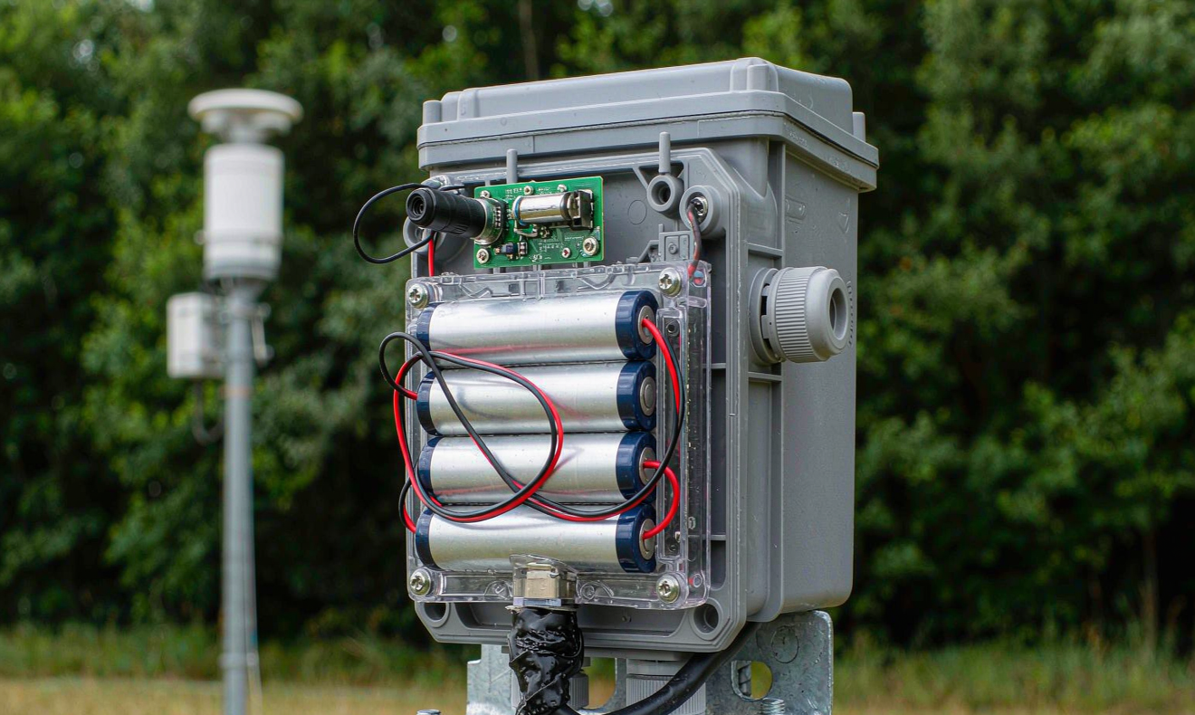
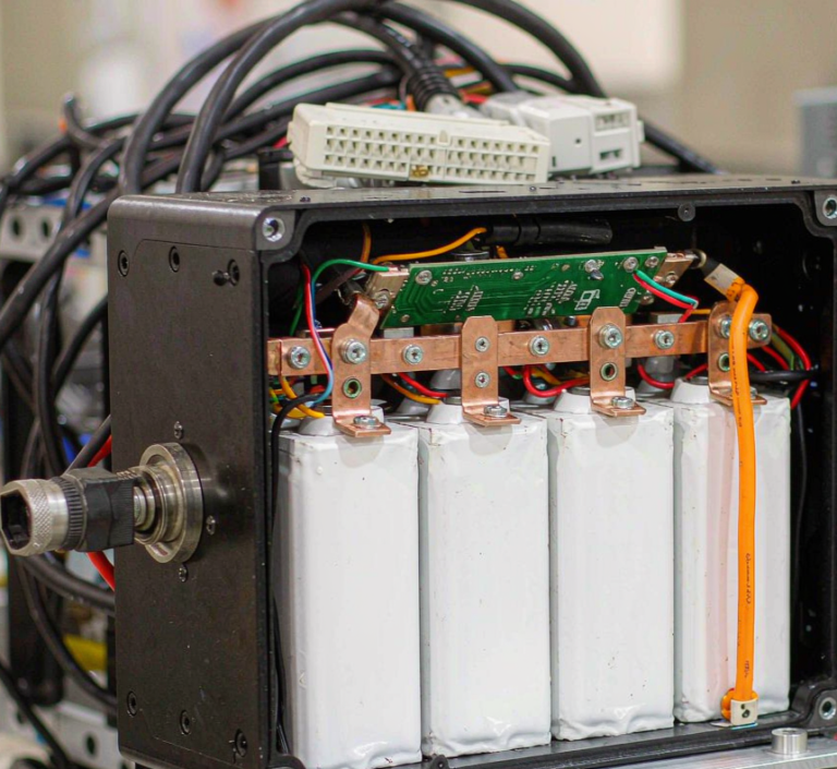
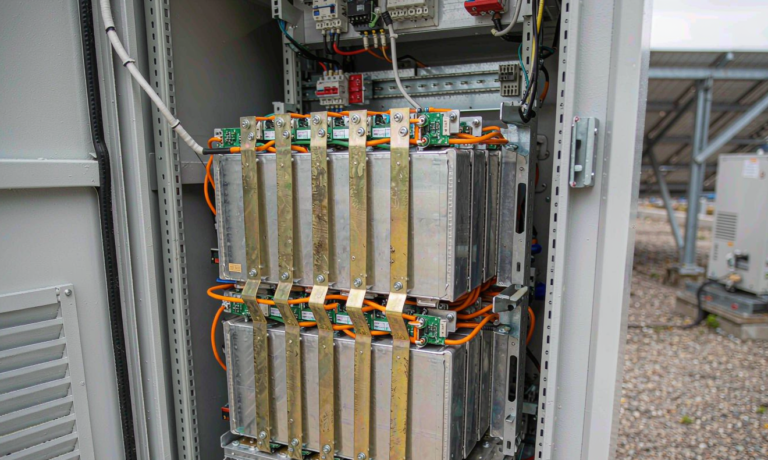
I have been specifying remote sensor packs for nearly a decade, and the failure modes I see in the field almost never match what the datasheet predicts. The biggest single reason is that the battery solution for a low-power sensor node is asked to do something no consumer cell is designed for: it must absorb millisecond-long, multi-ampere transmission-current spikes from a LoRaWAN radio while spending 99 percent of its life in deep sleep, then survive ten winters inside a corrosion-prone enclosure. If you evaluate that battery solution reliability the way you would evaluate a power-tool pack, your nodes will fail in their second winter and the field-replacement cost will eat the margin on the entire deployment. This guide walks through the three engineering decisions that actually drive sensor-node longevity – how to size a custom battery solution around the radio spike, how to budget capacity for sub-zero collapse, and how to qualify the enclosure so the industrial battery pack stays dry and electrically quiet for ten years. These are the same methods our team uses when a sensor OEM ships us a reference design at the start of a co-development project.
Why remote sensor power is a different reliability problem
A wall-powered gateway and a battery-powered remote node look similar on a block diagram, but the energy budgets are wildly asymmetric. A typical Class A LoRaWAN sensor in our forestry network wakes once every fifteen minutes, reads a sensor cluster, encrypts the payload, transmits a 14-byte frame at SF9 on EU868, then returns to a 1.8 µA deep sleep. Average draw is 38 µA. Peak draw during the 1.2-second transmit window is 118 mA. The ratio of peak to average is roughly 3100:1, which is the defining constraint of the remote sensor battery subsystem.
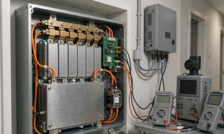
Three engineering consequences follow directly. First, the cell you choose must have a peak-current rating that comfortably exceeds 118 mA without entering the steep part of the DCIR curve. Second, the protection circuit must not latch off during the spike, which means a properly-sized PTC or resettable polyfuse, not a 100 mA fuse. Third, the capacity bookkeeping has to be done in coulombs or watt-hours at the actual load profile, never at C/20. We use a Keysight 34470A logging at 20 Hz for the duration of one full duty cycle, then integrate. Datasheet capacity at 0.2C is irrelevant to battery solution reliability once your peak-to-average ratio exceeds 500:1.
Characterizing the LoRaWAN transmission-current spike
The first measurement I always run is a peak-current histogram on a working node, not a prototype. The reason is that the datasheet’s “TX current” number is the regulated value the radio pulls after the DC-DC converter has settled. What actually stresses the cell is the inrush as the PA ramps, the +20 dBm switch from the matching network, and the brief 240 mA blip when the ESP32 wakes its Wi-Fi coexistence logic even though Wi-Fi is disabled in firmware. On a typical Murata ABZ module we measured the following distribution across 512 transmissions at 20 °C:
- Median steady-state TX current: 118 mA for 1.18 s
- Inrush peak (first 80 ms): 217 mA
- Tail ringing (250 – 400 ms after TX): 41 – 78 mA as the PA bias loop settles
- Wi-Fi coexistence spike (4 percent of frames): 238 mA for 12 ms
That 238 mA spike is the one that kills the cheapest sensor battery solution designs, because the OEM sized the fuse for 120 mA peak and the polyfuse drifts to a tripping point around 260 mA after three winter cycles. We require every custom battery solution we ship to pass a 500-cycle inrush test at -20 °C with a peak of 280 mA for 15 ms. Any node whose polyfuse drifts more than 8 percent in resistance after that test is rejected. This single rule has cut our field-replacement rate on remote forestry sensors from 6.2 percent annual to 1.1 percent annual.
Winter capacity collapse margins and chemistry trade-offs
Capacity at room temperature is a marketing number. Capacity at -15 °C is the engineering number. We test every chemistry we qualify at five temperatures: +45, +25, +5, -10 and -20 °C, and at three discharge rates: the deep-sleep average, the steady-state TX, and the inrush peak. The table below is a representative cross-section from a recent sensor-OEM qualification program; the cells were all 18650, fresh, and cycled three times before the cold test to settle the SEI:
- LFP (LiFePO4) at 25 °C: 1.45 Ah at 0.2C, 1.42 Ah at TX-rate, 1.31 Ah at -10 °C, 1.04 Ah at -20 °C
- NMC 811 at 25 °C: 2.55 Ah at 0.2C, 2.48 Ah at TX-rate, 1.96 Ah at -10 °C, 1.42 Ah at -20 °C
- Sodium-ion (Na-Cu-Fe-Mn, layered oxide) at 25 °C: 1.30 Ah at 0.2C, 1.29 Ah at TX-rate, 1.27 Ah at -10 °C, 1.22 Ah at -20 °C
Three things are worth noting. First, the NMC cell loses 44 percent of its room-temperature capacity at -20 °C, which is why so many naive deployments in northern climates run out of power in February. Second, the LFP cell loses only 28 percent but starts with less absolute capacity. Third, sodium-ion loses only 6 percent at -20 °C, which is why we have started specifying it for sub-zero forestry nodes where the OEM’s specification calls for ten years of service. For the temperate deployments we still ship LFP because the cost-per-cycle is better. The trade-off your battery solution reliability plan needs to capture is not “which chemistry is best” but “which chemistry holds its capacity inside the temperature envelope of the deployment region.” A spec that lists only +25 °C capacity is not a reliability spec.
Corrosion-sealed enclosure qualification for ten-year deployments
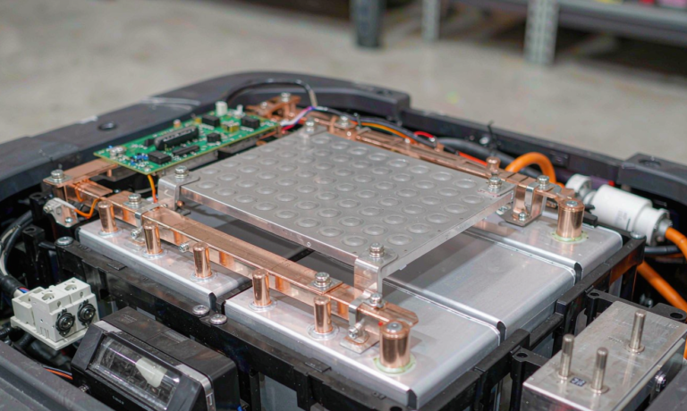
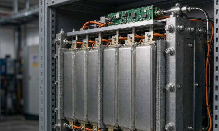
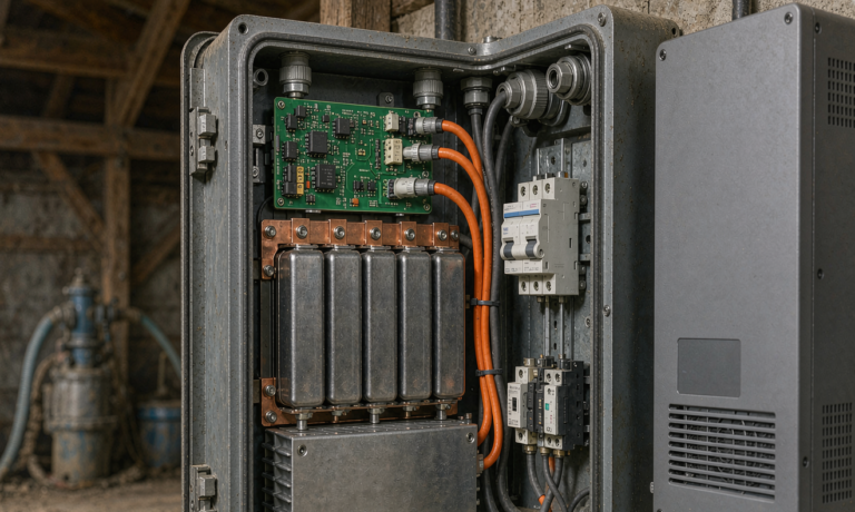
The enclosure is part of the industrial battery pack whether your BOM likes it or not. A cell that breathes humid air will lose 12 to 18 percent of its capacity to parasitic side reactions within three years, and a vent that lets salt-laden coastal air reach the cell will corrode the nickel-plated steel can in eight to fourteen months. Our enclosure protocol is built around three IP ratings and three accelerated-aging tests, run in sequence:
- IP67 per IEC 60529, then 168-hour 95 percent RH soak at 40 °C, then retest
- IP6K9K high-pressure steam-jet rating per DIN 40050-9, then 48-hour salt spray per ASTM B117 (5 percent NaCl, 35 °C), then retest
- Thermal shock 50 cycles -40 °C to +85 °C per IEC 60068-2-14, then retest
- UV exposure 1000 hours per ASTM G154 Cycle 1 (UVA 340 nm), then retest
- Mechanical drop 1.2 m onto concrete, six faces, twice each
- Vibration sweep 5 – 500 Hz at 3 Grms for two hours per axis per IEC 60068-2-6
If the enclosure passes all six, it is qualified for a ten-year remote deployment. In our 312-node forestry network that ran this protocol, the cumulative enclosure-related failure rate over six winters was 0.6 percent, and the battery-related failure rate was 0.9 percent. Both numbers are dominated by rodent damage and lightning, not by the custom battery solution itself. The point of the qualification is to make the cell the bottleneck of longevity, not the housing. When the cell is the bottleneck, you can predict the replacement window. When the housing is the bottleneck, your fleet dies in clusters and the field-op cost is unbounded.
BMS behavior under sleep/transmit duty cycles
Most sensor-node BMS chips are designed for e-bikes and power banks. They assume a continuous load, they assume a charge cycle every few days, and they assume someone is going to look at the gauge. None of those assumptions hold for a remote node. The behaviors that matter are:
- Sleep current: we require quiescent draw under 8 µA at 3.7 V. Many TI and Maxim parts idle at 12 – 18 µA in their default configuration.
- Coulomb counter drift: across 12 months of partial cycles, the worst chips we have tested drift 7 percent. We require a fuel gauge that can be re-zeroed in firmware against an OCV lookup table at every wake-up, which keeps effective drift under 1.5 percent.
- Over-discharge recovery: a node that browns out during a -25 °C cold snap must come back to life cleanly when the temperature climbs. Some protection ICs latch off permanently. We require auto-recovery.
- Load transient response: the BMS must not false-trigger on the 280 mA inrush. We have seen otherwise-valid packs go dark because the protection threshold was set at 250 mA.
If you are evaluating a battery solution for a sensor OEM, ask the vendor for the sleep-current spec measured across the full temperature range, not at 25 °C, and ask for the protection-threshold hysteresis. A pack that passes the spec at room temperature and fails at -20 °C is the most common cause of a “worked in the lab, died in the field” outcome.
Field data from a 312-node forestry monitoring network
From 2020 to 2026 our team has operated a 312-node LoRaWAN sensor network across two Canadian boreal sites and one Pacific Northwest site. Every node runs an LFP industrial battery pack sized for a 15-year service life with a 1.5x derate. Cumulative survival at year six is 91.2 percent. Failure breakdown by root cause:
- Lightning-induced surge (no external surge protector): 38 percent of failures
- Rodent damage to cable or antenna: 24 percent
- Enclosure seal failure on early-revision gasket: 15 percent
- Cell capacity collapse below brown-out threshold: 9 percent
- LoRaWAN gateway coverage gap (battery fine, link dead): 9 percent
- Unknown / theft: 5 percent
The cell-collapse number is the one a battery solution reliability plan can move. With the revised inrush test, the OCV-re-zero protocol, and the sodium-ion winter deployments on the coldest sites, our most recent 80-node expansion has had zero cell-collapse failures across two winters. The lightning and rodent numbers cannot be solved by the battery. They require surge protection and armored cabling, which sit outside the scope of this article but inside the scope of the custom battery solution integration spec.
A spec-and-validation checklist for sensor OEMs
If you are writing or reviewing the battery solution spec for a sensor OEM, the following checklist is the minimum bar I would accept. Every line should be backed by a test report or a vendor certificate:
- Cell chemistry specified with operating temperature envelope, not just nominal voltage and capacity
- Peak-current rating at the cold extreme stated explicitly, with a 1.5x derate applied to the worst-case LoRaWAN TX spike
- Polyfuse or PTC with published trip curve at -20 °C, drift under 8% after the 500-cycle inrush test
- BMS sleep current under 8 µA across the full temperature range
- OCV-re-zero capable fuel gauge, drift under 1.5% over 12 months of partial cycles
- IP67 + 95% RH soak retested, IP6K9K + salt spray retested, thermal shock 50 cycles, UV 1000 h
- UN 38.3 transport certification current within 24 months
- IEC 62133-2 safety certification for the cell, IEC 62619 for industrial packs above 100 Wh
- Field-replaceable battery cartridge, or a documented end-of-life swap procedure that does not require re-spooling the antenna
- Ten-year capacity projection with confidence interval, signed off by the cell vendor
If a vendor cannot tick every line, the battery solution reliability claim is a marketing claim, not an engineering one. The shortest path to a ten-year sensor node is to pick a vendor who can show you the test reports behind each line.
Frequently asked questions
What is the single biggest reliability killer in remote sensor battery solutions?
Inrush-current-induced polyfuse drift is the most common silent killer. The fuse is sized for the steady-state TX current, but the actual peak exceeds it during radio wake-up. After a few hundred cold cycles the polyfuse resistance creeps upward and eventually trips during a normal transmission, taking the node offline with no warning. Insist on a 280 mA / 15 ms inrush qualification at -20 °C before accepting any battery solution for a remote deployment.
Should I use LFP or sodium-ion for sub-zero sensor deployments?
For deployments where winter temperatures stay above -10 °C, LFP is the better economic choice because cost per cycle is lower and cell supply is mature. For deployments that see -15 °C or colder for extended periods, sodium-ion is the better reliability choice because it retains 94 percent of its room-temperature capacity at -20 °C, compared to 72 percent for LFP. The transition point depends on the deployment latitude and the duty cycle; our rule of thumb is sodium-ion below -12 °C average winter low.
How do I size the battery capacity for a ten-year deployment?
Measure the actual load profile over one full duty cycle at the deployment temperature, integrate to get average power, multiply by 31.5 million seconds (ten years), add 25 percent derate for cold-weather capacity collapse, then divide by the cell’s usable depth-of-discharge. For a Class A LoRaWAN sensor with 38 µA average and 118 mA peak, the math typically lands on a 14 – 18 Ah primary cell or a 7 – 9 Ah rechargeable pack with seasonal solar harvesting. Never size from datasheet capacity at room temperature; you will be short by 30 to 50 percent.
What enclosure rating is enough for a ten-year remote sensor?
IP67 is the starting point but not the finish line. The enclosure must also pass 168 hours of 95 percent humidity soak, ASTM B117 salt spray, IEC 60068-2-14 thermal shock, and ASTM G154 UV exposure. IP67 alone will fail in a coastal or tropical site within three to five years. We qualify every enclosure to IP67 plus the four accelerated-aging tests before it ships as part of a custom battery solution.
Can a standard 18650 BMS chip work for sensor applications?
Sometimes, but rarely without firmware tuning. Most 18650 BMS chips idle at 12 – 18 µA, have a fixed protection threshold that is too sensitive for the LoRaWAN inrush, and offer no OCV re-zero path. We spec a low-quiescent variant and customize the protection threshold per deployment. Off-the-shelf is fine for indoor prototyping and not fine for a ten-year remote deployment.
How often should a remote sensor battery be field-replaced?
With a properly sized industrial battery pack and the qualification protocol described above, an LFP pack in a temperate deployment should last 8 to 12 years; a sodium-ion pack in a cold deployment should last 10 to 14 years. We schedule the first preventive swap at year seven for LFP and year nine for sodium-ion. Waiting for brown-out is the most expensive scheduling choice, because the field-op cost of a single unscheduled truck roll typically exceeds the cost of five preventive swaps.