
Battery Solution Testing for Robotics: DVP&R, Duty-Cycle
When a robotics customer tells me their packs “passed all the battery tests” and then reports units dropping offline at 60% state of charge on the night shift, I already know what happened: the test plan measured the pack, not the application. Over the past decade of building custom battery solution programs for AMRs, cobots, inspection crawlers and unmanned ground vehicles, I have traced far more field failures to gaps in the validation plan than to defective cells. A cell that passes tidy 1C/1C cycling at 25 °C tells you very little about how it will behave under a 4C regenerative braking pulse at −5 °C in a cold-storage aisle, on hour nine of a three-shift day.
This article is the validation playbook I hand to robotics OEMs before we cut tooling: how to structure a DVP&R (Design Verification Plan and Report), how to build duty-cycle emulation from real robot logs, which safety and EMC standards actually apply, what end-of-line testing must catch, and the evidence package to demand from any battery solution supplier. The aim is not longer testing — it is predictive testing.
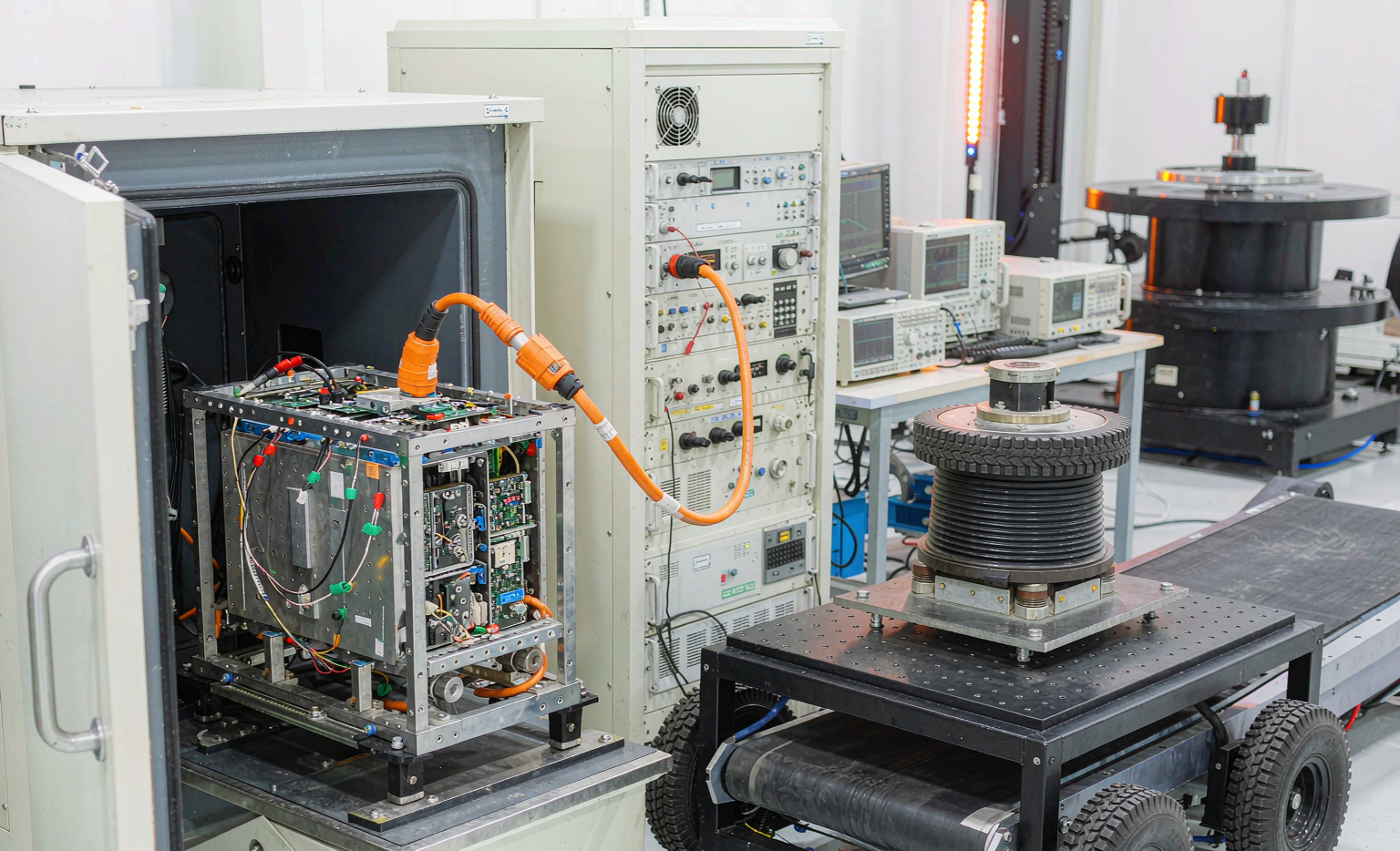
Why Generic Battery Testing Misses Robotics Field Failures
Most robotics battery test plans I inherit were copied from a consumer lithium battery program and stretched to fit a 48 V industrial machine. They typically fail in three places.
- Voltage sag and nuisance undervoltage trips. Constant-current discharge at 0.5C never reproduces the 2-second, 90–130 A stall pulse a robot draws when a drive wheel binds on a floor joint. With a pack DC internal resistance of 30–45 mΩ, that pulse costs 2.7–5.9 V at the terminals. If the BMS undervoltage lockout has no pulse debounce, the robot shuts down at an indicated 25–30% SoC — with nothing wrong with the cells.
- Connector and contact fatigue. A docked AMR mates its charge contacts 8–14 times per day, roughly 12,000–15,000 insertion cycles over three years. Blade and pogo contacts rated for 5,000 cycles climb from 2 mΩ to 15–25 mΩ, causing dock heating and charge derating that operations reads as “battery getting weak”.
- Thermal accumulation in a sealed chassis. Robotics packs live in IP54 or IP65 compartments with no forced airflow, while bench cycling on an open shelf dissipates heat the real machine cannot. I have measured 14–19 °C higher core temperature on the same pack once installed in the customer’s enclosure — a delta that alone can double five-year fade.
Each is cheap to find in week six of validation and expensive in month six of deployment.
Structuring the DVP&R: Requirements Before Test Cases
A test plan that begins with a list of tests is already broken. It has to begin with quantified requirements, flow through a DFMEA, and only then generate test cases with numeric acceptance criteria.
For a typical warehouse AMR battery solution the requirement set reads: 48 V nominal (13S), 30 Ah usable at 25 °C after 1,500 equivalent full cycles, 120 A continuous / 200 A for 10 s, 0–45 °C charge and −20–50 °C discharge windows, 80% SoH at five years, IP65, 22 kg mass ceiling. Each becomes a test case with a numeric pass threshold.
The DFMEA then drives the abuse and fault-injection cases. If “open cell voltage sense wire” scores a severity of 9, a test must physically cut that wire and verify the pack enters a safe state. I insist on two-way traceability: every failure mode with severity ≥ 7 maps to a test case, and every test case maps back to a requirement.
On sample sizes, my defaults are six packs for design verification from soft tooling and three for production validation from hard tooling. A zero-failure demonstration at 90% reliability and 90% confidence needs 22 units, which is impractical at pack level, so we run that statistically at cell level and apply Weibull analysis with acceleration factors at pack level.
Duty-Cycle Emulation: The Single Highest-Value Test You Are Probably Skipping
This is where robotics battery solution testing earns its keep. Instead of cycling at constant current, we log the real machine and replay it on the cycler.
The procedure: instrument two or three production-intent robots with a 1 Hz (ideally 10 Hz) current and voltage logger for a full week across all shifts, then extract a representative 8-hour composite profile. A recent AMR project produced this shape:
- Idle and standby: 0.6–1.1 A
- Travel at nominal speed: 11–18 A
- Acceleration and slope peaks: 45–75 A for 2–4 s, roughly 340 events per shift
- Lift or conveyor actuation: 28–34 A for 5–8 s
- Regenerative braking: −15 to −24 A for 1–2 s, about 300 events per shift
- Opportunity charging at the dock: 0.5C bursts between 35% and 80% SoC, 6–9 times per shift
Total throughput came to 21.4 Ah per shift, or 2.3 equivalent full cycles per day. That number converts a five-year life requirement into a concrete 1,500-cycle test target, and it also tells you whether a 3,000-cycle LFP cell is genuinely necessary or whether a well-managed NMC lithium battery clears the target comfortably.
We then run that profile at 0 °C, 25 °C and 45 °C with at least three packs per condition, to 80% SoH or 1,500 cycles. Capacity and 10-second pulse DCIR are measured every 100 cycles under identical reference conditions. In my experience the gap between datasheet 1C cycle life and duty-cycle-emulated life runs 20–40% — designing against the datasheet number is how fleets end up needing an unbudgeted mid-life pack replacement.
Environmental, Vibration and Mechanical Testing
Robots vibrate constantly, get slammed into dock plates, and move between loading bays and freezers. The mechanical and environmental block should reflect that.
- Thermal cycling: IEC 60068-2-14 Test Na, −20 °C to +60 °C, 50 cycles, 30-minute dwells, with a functional check at each extreme rather than only at the end — intermittent solder and connector faults appear hot or cold, then hide at ambient.
- Damp heat: IEC 60068-2-78, 60 °C at 93% RH for 21 days, then insulation resistance measurement. Anything below 10 MΩ at 500 VDC fails.
- Random vibration: 10–500 Hz at approximately 0.04 g²/Hz PSD, eight hours per axis in three axes, referencing SAE J2380 and ISO 12405 profiles. UN 38.3 Test T.3 (7–200 Hz sinusoidal, 3 hours per axis) is a transport requirement, not a service-life requirement — you need both.
- Mechanical shock: UN 38.3 T.4 at 150 g / 6 ms for small packs, plus a 1.0 m drop onto concrete in the orientation the operator will actually drop it, per IEC 62133-2.
- Ingress protection: IEC 60529 IP65 testing performed after vibration and thermal cycling, never before. Sealing that passes on a virgin sample then fails after shaker time is the most common surprise here.
Safety and Abuse Testing: UN 38.3, IEC 62619 and Robot-Specific Standards
Certification testing is the floor, not the ceiling, but it must be scoped correctly from day one because retesting is slow and expensive.
Transport qualification is UN 38.3 tests T.1 through T.8: altitude, thermal cycling, vibration, shock, external short, impact or crush, overcharge and forced discharge. Since 2020 the test summary must be made available, so I treat it as a deliverable rather than a file the factory keeps. Shipping follows IATA Packing Instruction 965 with a 30% state-of-charge ceiling — a rule I learned the hard way on drone battery air freight, and one that applies identically to robotics packs.
Product safety depends on pack size and application: IEC 62133-2 for portable and hot-swap packs, IEC 62619 for industrial secondary lithium batteries including its thermal-propagation clause, UL 2580 for larger traction packs, and UL 9540A methodology if the same chemistry is proposed for stationary storage. Machine-level standards layer on top — ISO 3691-4 for driverless industrial trucks, ISO 10218 with ISO/TS 15066 for collaborative applications.
Beyond certification I run a single-cell thermal-propagation trigger on at least one production-intent pack, using a heater or nail penetration on a worst-case internal cell. Acceptance criteria are unambiguous: no flame or explosion outside the enclosure, no propagation beyond adjacent cells, EUCAR hazard level 4 or lower. Overcharge runs at 1C to 130% SoC or until protection acts; external short circuit at under 5 mΩ with case surface below 150 °C. This is the data that gets a safety officer to sign off.
BMS Functional and Fault-Injection Testing
In robotics, most “battery failures” are actually BMS behavior failures. A hardware-in-the-loop bench with a multichannel cell simulator lets you test the firmware properly instead of hoping.
Threshold verification comes first: overvoltage at 4.25 V ±25 mV per cell, undervoltage at 2.80 V with 200 ms pulse debounce, overcurrent discharge at 120 A held 200 ms before trip, charge overtemperature 60 °C and discharge 70 °C, all with documented hysteresis. Then fault injection: open a sense wire, short and open a thermistor, force a stuck-on FET, weld a contactor, drop the CAN bus mid-charge, brown out the supply during a firmware update. Each case must land in a defined safe state and report a diagnostic code the fleet software can act on.
Two accuracy requirements matter most for uptime. State-of-charge error must stay within 3% across the full duty profile at all three test temperatures — coulomb counting alone drifts to 8–12% under regenerative pulses, so the estimator needs voltage-based correction or a model. State-of-health should track measured capacity within 5%, because SOH drives your maintenance schedule and warranty position. I also verify balancing convergence: a deliberate 60 mV cell spread should close to under 20 mV within 24 hours of normal charging.
EMC Testing With the Radios and Motors Switched On
A robot is an electromagnetically hostile place: a motor drive switching tens of amps, a lidar, a Wi-Fi or 5G radio, and a pack with thin analog sense lines, all within half a metre. Emissions testing to CISPR 11 / EN 55011 Group 1 Class A is straightforward. Immunity is where packs fail.
My minimum immunity set is IEC 61000-4-2 ESD at ±8 kV contact, 61000-4-4 EFT bursts, 61000-4-5 surge on the charge port, 61000-4-6 conducted RF at 10 V, and 61000-4-3 radiated immunity at 10 V/m from 80 MHz to 3 GHz — all run while the pack is actively charging and discharging, not idle. On one inspection-robot program a 3 V/m field at 900 MHz coupled into an unfiltered NTC line, produced a phantom 78 °C reading and triggered a thermal shutdown mid-mission. The fix was trivial — a 100 nF capacitor at the thermistor input, a ferrite on the harness, a median filter in firmware — but finding it after launch would have meant a fleet-wide recall.
Production Testing: ATP, End-of-Line and Traceability
Design validation proves the design. Production testing proves each unit. A custom battery solution needs both, and the second one runs forever.
- Incoming cells: 100% open-circuit voltage and AC internal resistance sorting into groups within ±10 mV and ±0.5 mΩ, plus a sampled capacity audit per lot.
- In-process: destructive weld pull tests on sampled tabs (30 N minimum for nickel strip on 21700) and micro-ohmmeter joint resistance checks with a 0.05 mΩ deviation limit against the golden sample.
- End-of-line: hipot and insulation resistance, partial capacity and DCIR verification (a 10% depth pulse catches outliers without consuming cycle life), BMS parameter and firmware readback, CAN identifier confirmation, full functional charge and discharge.
- Aging screen: 48–72 hours of storage with self-discharge monitoring, rejecting anything above roughly 2 mV per day. This single screen catches most latent internal-short defects before they leave the building.
- Traceability: cell lot to module to pack serial, bound to a data-matrix code and retained ten years. When a field failure appears in year three, this is the difference between quarantining nine packs and nine hundred.
I also ask for statistical capability, not just pass/fail. Weld resistance and delivered capacity should show a Cpk of 1.33 or better; a line that only reports “100% pass” has no visibility into drift.
The Evidence Package to Demand From Your Supplier
Before releasing a robotics battery solution to production, require the following as contract deliverables:
- The complete DVP&R matrix with measured values, not “pass” checkmarks
- Raw cycler data files from duty-cycle emulation, at all test temperatures
- UN 38.3 test summary, plus IEC 62133-2 or IEC 62619 (and UL 2580 where applicable) certificates with the scope page showing your exact configuration
- The full EMC report including immunity results taken under load
- Thermal-propagation test report with video and thermocouple traces
- The production control plan, gauge study data, and Cpk figures for critical characteristics
- The BMS fault-injection matrix with observed safe states and diagnostic codes
Good testing is not about accumulating reports. It is about deliberately provoking, in a lab, the failures your fleet would otherwise find on a Tuesday night shift. Every robotics lithium battery program I have seen go smoothly spent its schedule at the front, on duty-cycle emulation and fault injection, not at the back on field firefighting.
Frequently Asked Questions
How long does a full robotics battery validation program take?
Fourteen to twenty-two weeks for a new custom battery solution. Cycle life is the long pole: 1,500 emulated cycles at roughly 2.3 cycles per test day runs about 11 weeks even with parallel channels. Safety and EMC take four to six weeks including lab scheduling; everything else runs concurrently.
Can I reuse an existing UN 38.3 report if I change the cell?
No. A cell change requires new UN 38.3 testing, as does a change in cell count, series-parallel configuration or protective circuitry. Enclosure and BMS changes usually need at least a difference assessment by the lab. I budget 2,500 to 6,000 USD and three to five weeks for a retest, and lock the cell decision early to avoid one.
Is duty-cycle emulation really necessary when the datasheet already shows 2,000 cycles?
Yes. Datasheet cycle life is measured at a constant, benign rate at 25 °C with full-depth cycles. Real robots deliver high-rate pulses, partial-depth opportunity charges and elevated in-enclosure temperatures. Across my projects, emulated cycle life lands 20–40% below the datasheet figure — the most common reason a fleet needs unplanned pack replacements at year three.
What sample size should I use for cycle-life testing?
Three packs per condition is the practical minimum, five if budget allows, because 5–8% pack-to-pack spread in cycle life is normal. At cell level use ten cells per group for meaningful Weibull confidence. One pack per condition produces a data point, not a distribution, and cannot support a warranty position.
How can we validate opportunity charging without waiting a year?
Two levers. First, compress calendar time using measured Ah throughput — a fleet averaging 2.3 equivalent cycles per day compresses five years into about 1,500 test cycles, which a cycler completes in weeks. Second, apply moderate thermal acceleration, typically 45 °C against a 30 °C field average, for an Arrhenius acceleration factor of roughly 2 to 3 on calendar fade. Validate that factor against an ambient control group, and never accelerate past 50 °C, where degradation mechanisms change and the extrapolation breaks down.





