Lithium Battery Manufacturing for Mobility Devices
I have spent most of my career on the manufacturing side of the battery business, and there is one product category that consistently punishes sloppy production engineering more than any other: batteries for personal mobility devices. Electric wheelchairs, mobility scooters, power-assist add-ons and rehab carts look like simple low-voltage products on paper, but from a production standpoint they are unforgiving. A pack that fails in a consumer gadget annoys the user. A pack that fails in a mobility device strands a person, sometimes in traffic, sometimes in a doorway, sometimes three kilometres from the charger.
This guide is my shop-floor view of how a lithium battery for mobility devices should actually be built. It is written for OEM engineers, sourcing managers and quality leads who need to understand what happens between the cell arriving at the goods-in dock and the finished lithium battery pack passing its final electrical test. Everything here comes from programmes I have run or audited: cell matching, joining, insulation, BMS integration, sealing, end-of-line test, traceability and the standards that quietly dictate most of the line layout.
Why mobility devices are a distinct manufacturing problem
A mobility pack is not a scaled-down EV pack and it is not a ruggedised power bank. It sits in an awkward middle ground. Terminal voltages are usually 24 V or 36 V nominal (7S or 10S LFP, 7S or 10S NCM), capacities run from 6 Ah to 40 Ah, and the duty cycle is brutal: deep discharges almost every day, partial recharges, long idle periods, and a user population that cannot be expected to perform any maintenance beyond plugging in a charger.
From a process design perspective, four constraints drive almost every decision I make on a mobility programme:
- Life-critical availability. The device is a person’s legs. Field failure rates must be measured in single-digit ppm, not the several hundred ppm that a consumer product can absorb.
- Low voltage, high current. A 24 V pack delivering 1.2 kW is pulling 50 A. Every milliohm in the interconnect counts, and a marginal weld that looks fine at 5 A will cook at 50 A.
- Harsh mechanical environment. Kerb strikes, thresholds, ramp transitions and constant vibration. IEC 60068-2-6 sinusoidal vibration and IEC 60068-2-64 random vibration profiles are not box-ticking exercises here.
- Chronic over-spec of the user. Real-world loads exceed the marketing datasheet. I routinely see scooters drawing 20–30% more peak current than the nominal motor rating because of tyre pressure, rider mass and hills.
Designing a custom battery solution for this category therefore means the manufacturing line has to prove, part by part, that the pack will survive a decade of abuse without notice. That proof is built in process steps, not in an inspection gate at the end.
Cell incoming quality control and matching
Everything downstream depends on cell consistency. Whether the programme uses an LFP battery chemistry for cycle life and safety or an NCM battery chemistry for energy density, I buy cells to a written incoming specification, not to a datasheet. The incoming inspection I require on every lot includes capacity verification at 0.5 C and 25 °C per IEC 61960, internal resistance measurement (both ACIR at 1 kHz and a DC pulse method), open-circuit voltage, visual inspection of the can and the laser weld at the vent, and dimensional checks on the positive terminal face.
Capacity and DCIR grading
Cells are graded into bins. On a mobility programme I hold capacity spread to within ±1.5% of the mean within a pack and DCIR spread to within ±8%. Cells outside the band do not get scrapped; they go into lower-tier products or into service packs. The reason is simple: in a series string, the weak cell sets the pack’s usable capacity, and the high-resistance cell sets its thermal behaviour. A 3% capacity mismatch at build becomes a 6–8% mismatch after 800 cycles, and that is when you start getting nuisance cut-offs on hills.
Self-discharge screening and the K-value
After formation at the cell maker, good cells continue to be screened on the line through a rest period. I measure OCV at the start and end of a controlled storage window and convert it to a K-value in mV/day. Premium cells come in well under 0.05 mV/day; anything drifting higher is a micro-short or a metal-particle contamination risk. This is the single cheapest screening step in the whole process and the one most often skipped by contract manufacturers working to a price. It should never be skipped on a mobility build.
Busbar joining: resistance spot welding versus laser welding
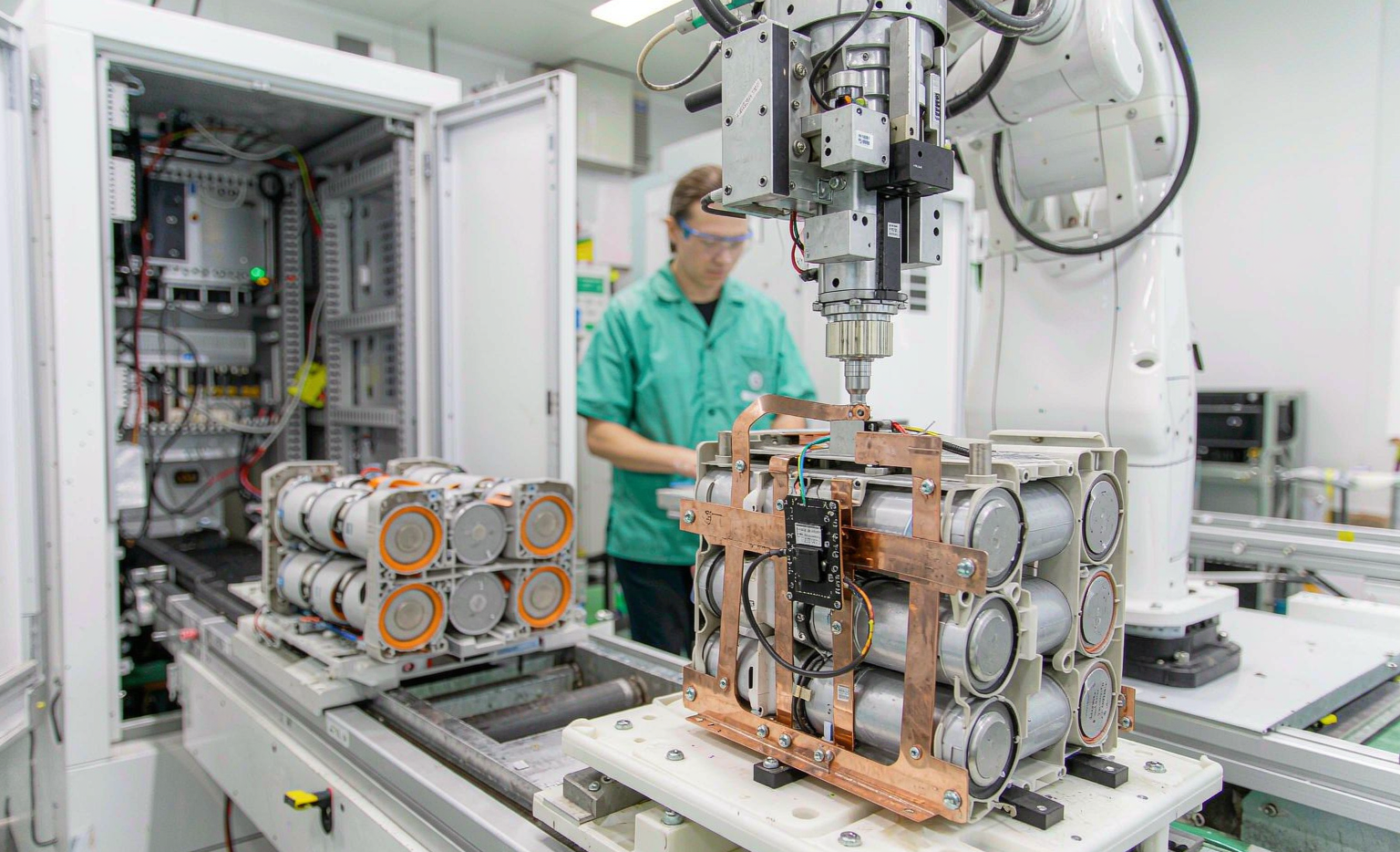
Nickel-plated steel or pure-nickel strip to cell terminal is the classic junction, and it is where most latent field failures are born. I develop the weld schedule the same way every time: build a weldability lobe per ISO 14327, then verify with destructive peel testing per ISO 14270 and failure-mode classification per ISO 14329.
Acceptance criteria I hold on mobility packs:
- Peel strength. Minimum 40 N for a 0.15 mm nickel strip, with the failure mode required to be a nugget pull-out (material tears around the weld) rather than interfacial fracture (the nugget lifts clean off the can).
- Nugget coverage. At least 60% of the intended interface area, verified by microsection on a sample basis.
- Heat-affected zone control. The cell’s internal polymer seal and separator must not see the temperature that causes shrinkage. In practice that means a weld energy window of roughly 15–25% between “no weld” and “damaged cell”, and daily coupon verification to prove the welder has not drifted.
- Current-path symmetry. Welds arranged so that current density is even across the strip; asymmetric weld pairs create local hot spots that show up as discolouration after 500 cycles.
Laser welding is the better answer for aluminium or copper busbars on high-current packs, and increasingly for mobility scooters with 100 A peak draws. It gives a continuous seam, lower joint resistance and no electrode wear — but it demands far tighter part fit-up, an inert gas shield and 100% cosmetic plus pull-test verification. I use laser when the pack is above roughly 1.5 kW continuous, and resistance welding below that, where the cost-benefit is clear.
Insulation, mechanical retention and vibration robustness
Cell holders are not just spacers. On a mobility pack the holder sets the creepage and clearance distances, maintains cell spacing for thermal reasons, and carries the vibration load. I specify holders in UL 94 V-0 rated material, with a glass-filled grade above 60 °C ambient. Fish paper or a formed PET barrier between the positive terminal array and the busbar plane is mandatory in my designs, not optional — I have investigated too many field shorts traced to a ring of burrs or a dropped washer.
The mechanical validation sequence I run before tooling sign-off:
- Sinusoidal vibration per IEC 60068-2-6 across 10–55 Hz, 30 minutes per axis, with the pack energised and monitored for impedance jumps.
- Random vibration per IEC 60068-2-64 using a scooter-derived PSD, 3 hours per axis — this is the test that finds undersized weld tabs.
- Mechanical shock per IEC 60068-2-27, 30 g half-sine, 18 ms, 3 shocks per direction, which is a good proxy for kerb strikes.
- Post-test hipot verification and full functional test. A pack that passes electrically before vibration and fails after is a mechanical design failure, not an electrical one.
BMS integration and wiring harness assembly
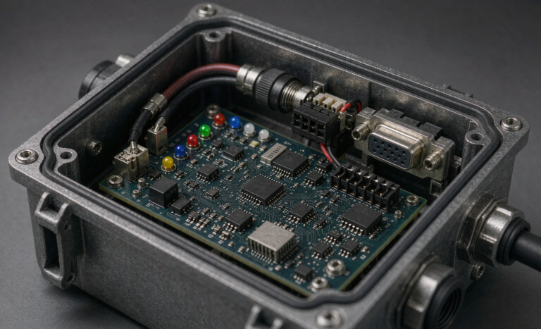
The BMS is where the pack’s behaviour is defined, and on mobility devices it must be conservative. I specify balance currents of 60–100 mA for packs up to 30 Ah, configurable over-voltage and under-voltage thresholds per the cell maker’s specification (never per the marketing datasheet), and a pre-charge circuit on any pack feeding a motor controller with more than a few hundred microfarads of input capacitance. Skipping pre-charge is the most common cause of welded contactor and MOSFET failures I see in the field.
On the assembly side, the harness is built to IPC-A-620 Class 2, and any BMS board rework to IPC-A-610. Sense leads are individually fused or resistively limited at the board, routed separately from the power path, and strain-relieved at both ends. I insist on 100% automated optical inspection (AOI) plus X-ray on the BMS-to-busbar joints, because an unterminated balance lead is invisible to the eye and catastrophic to the pack.
A good BMS solution for mobility also needs to be honest about state of charge. Coulomb counting drifts badly with the partial-cycling pattern these devices see. On every programme I now require a hybrid estimator — coulomb counting corrected by OCV lookup at rest and by a learned resistance model under load — and I validate it over a two-week real-usage trace before release.
Sealing, potting and ingress protection
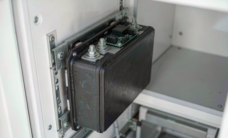
Ingress protection is a design decision with manufacturing consequences. IP54 per IEC 60529 is achievable with gaskets and a well-designed clamshell. IP65 and above require potting or a welded enclosure, and potting removes any possibility of service. For wheelchairs and scooters, my default is IP54 for indoor-outdoor devices and IP65 with a serviceable gasketed cover for devices used in all weather.
Where potting is used, the process controls that matter are: substrate temperature before dispense, vacuum degassing of the two-part compound, a controlled cure profile (not “leave it on the rack overnight”), and a validated potting depth that covers the joints without burying the thermal sensor or blocking the vent path. Blocking a cell vent path with compound is a serious safety error, and I have seen it done by otherwise competent assembly houses.
End-of-line testing
End-of-line test is where the manufacturing process is either confirmed or exposed. My standard EOL sequence for a mobility lithium battery pack runs in this order:
- Insulation resistance and hipot. Typically 500 V DC for one minute between the pack terminals and the enclosure or the accessible conductive parts, with a leakage limit of a few milliamps. This is the test that catches stray strands and pinched insulation.
- Polarity and wiring verification. Every sense lead is read back in sequence. A transposed sense lead on a 10S pack is caught here or not at all.
- BMS functional test. Simulated over-voltage, under-voltage, over-current, short-circuit protection and thermal cut-off, each verified as a state change on the communications line.
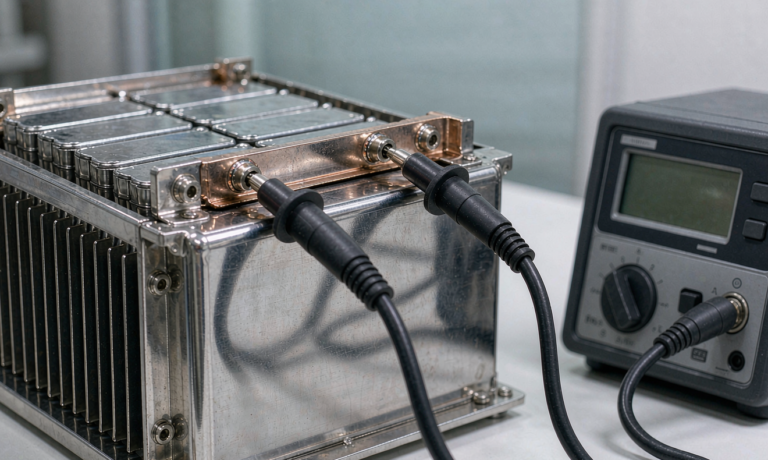
- Capacity verification. A 1 C discharge to cut-off with a capacity window of ±3% of nominal, plus a DCIR measurement at 50% SoC. I log this value and use it as the pack’s birth record.
- Charge acceptance. Full CC/CV charge with the production charger, verifying termination current and end-of-charge temperature rise below 15 °C.
Testing to this depth costs time — 40 to 90 minutes per pack depending on capacity, which is why formation and ageing are capacity-planned as a separate bank rather than in-line. It is worth every minute. Field returns on programmes with this sequence run at a fraction of those with a “voltage and go” EOL.
Traceability, MES and the EU battery passport
Traceability on mobility packs is now a legal matter, not just a good practice. Under EU Regulation 2023/1542, industrial and light means of transport batteries above 2 kWh move to a digital battery passport, and the data obligations — material composition, carbon footprint, recycled content, performance and durability parameters — start being enforced from 2027. Even for packs below the threshold, my customers selling into Europe are building the data now.
Practically, that means a manufacturing execution system that binds cell lot, weld machine ID and weld schedule revision, BMS firmware version, operator, EOL test results and the pack serial number into one record. I use 2D data matrix codes verified to ISO/IEC 15415 print quality, because a code that cannot be read at a service centre five years later defeats the purpose. The same system makes recall scopes surgical: instead of pulling 20,000 packs, you pull the 300 that share a suspect cell lot.
Compliance that shapes the line
Several standards are not simply certificates to hang on a wall; they determine process steps.
- UN 38.3 (T1–T8) and the IATA DGR 30% state-of-charge limit for air transport under UN3480 govern how packs are shipped, and they dictate the pre-shipment conditioning step on my lines.
- IEC 62133-2 is the baseline safety standard for sealed portable secondary cells and batteries, and its design and test requirements drive choices around venting, creepage and clearance.
- UL 2271 covers batteries for light electric vehicle applications and is the practical requirement for a mobility scooter lithium battery sold in North America; UL 2849 covers the complete electrical system when the pack is sold with the vehicle.
- EN 12184 covers electrically powered wheelchairs, scooters and their chargers in Europe, and ISO 7176-14 and ISO 7176-21 address power and control systems and electromagnetic compatibility respectively.
- IEC 60335-2-29 applies to the battery charger, which is part of the same safety story even though it is a separate product.
- IEC 62619 becomes relevant for industrial mobility — automated guided vehicles and warehouse carts — where the application is industrial rather than personal.
On top of the product standards, a credible lithium battery manufacturer holds ISO 9001 and ISO 14001, controls ESD to ANSI/ESD S20.20, and runs a dry room or dehumidified cell store with a documented dew-point limit. These are the things I check first when I audit a supplier, and the things my customers check first when they audit me.
Design-for-manufacturing checklist for OEM programmes
When a customer brings me a mobility programme, I walk through the same list before quoting tooling:
- Can the pack be assembled without forcing a weld head into a corner? If not, the mechanical design needs to change before the tooling does.
- Is there a defined first-article process with dimensional, electrical and destructive analysis reports, plus a signed golden sample?
- Are the cell maker’s exact charge and temperature limits implemented in the BMS, with margin, rather than the cell reseller’s summary sheet?
- Is the service strategy defined — field-replaceable pack, field-replaceable module, or return-to-factory? This determines whether potting is permitted.
- Is there a defined end-of-life and a take-back route, which is now a regulatory requirement in the EU rather than a sustainability talking point?
- Has the pack been validated against a real usage trace, not a laboratory duty cycle?
Frequently asked questions
How long does it take to build a production line for a custom mobility battery pack?
From design freeze to a validated first article, expect 10 to 14 weeks. That breaks down roughly as four weeks for tooling and fixture build, two weeks for the first-article build and destructive analysis, three to five weeks for safety and transport certification, and the remainder for EOL test development and pilot run. Programmes that try to compress this by skipping the pilot run almost always pay for it twice in field returns.
Should I choose LFP or NCM for a mobility device pack?
For most wheelchairs and scooters, I recommend LFP. The energy density penalty of roughly 30–40% at cell level is largely recovered at pack level because LFP tolerates a wider state-of-charge window and needs less thermal management. LFP routinely delivers 3,000 to 6,000 cycles to 80% capacity against 800 to 1,500 for NCM, and it is far more forgiving of the abuse these devices see. I specify NCM only when the device is weight-critical, such as a foldable travel scooter lifted into a car boot.
Why does my pack lose capacity faster in winter and recover in spring?
That is normal electrochemistry, not degradation. At 0 °C the usable capacity of a lithium ion battery drops by 15–25% because of increased internal resistance and slower lithium diffusion, and the BMS will cut off earlier under load. Capacity returns as the cells warm. The real winter risk is charging below 0 °C, which causes lithium plating and permanent damage. A pack with a charge-temperature interlock and, ideally, a self-heating function, prevents it.
What is the most common manufacturing defect you find in field-returned mobility packs?
Marginal welds. A nugget that is 10% undersized passes every electrical test at room temperature, then creeps and cracks under thermal cycling and vibration. The second most common is moisture ingress through a gasket that was compressed once at assembly and never re-seated after a service visit. Both are process problems, not design problems.
Can a mobility pack be repaired, or must it be replaced?
It depends entirely on the build strategy. A gasketed, non-potted pack with a bolted internal structure and documented service torque values can be repaired at cell or BMS level by a trained technician. A potted pack cannot. I always tell customers that choosing IP67 potting is also choosing a replace-not-repair strategy, and that decision should be made with the total cost of ownership in front of you.
How do I verify a supplier is actually doing proper cell matching?
Ask for the EOL data set from a production batch: per-pack DCIR mean and standard deviation, per-pack capacity spread, and the K-value distribution of the cells used. A manufacturer doing real matching will hand you these numbers within a day because the MES already has them. A manufacturer guessing will offer you a certificate instead.
What documentation should ship with every pack?
At minimum: the UN 38.3 test summary, the IEC 62133-2 or UL 2271 certificate, the pack’s individual EOL test record, a declaration of conformity, the transport classification and state-of-charge statement, and a service manual with torque values and the BMS parameter set. If the pack is going to Europe, add the material and recycled-content data required for the battery passport.
Is a 12 V lithium battery ever the right choice for a mobility device?
Almost never for the traction pack. A 12 V lithium battery makes sense for auxiliary loads — lighting, a lift actuator, a control display — but traction at 12 V means currents high enough that connector and cable losses dominate. Traction packs belong at 24 V or 36 V nominal, with a DC-DC converter feeding the auxiliary rail.