Lithium Battery Performance for Power Tools: Pulse-Duty
When a contractor drives a 40V brushless circular saw through a stack of OSB and the motor bogs down on the last third of the cut, the complaint is always the same: “the battery went weak.” As a senior lithium battery engineer who has spent over a decade building high-drain packs for OEM power-tool brands, I hear this weekly. But the pack did not “go weak” in the way most people imagine. What the user felt was the pack crossing a very specific performance boundary — the end-of-discharge voltage-sag knee during a high-current pulse. That boundary, not the printed amp-hour rating, is what lithium battery performance power tools is really about. My published guide on what engineers measure covered the headline metrics; here I want to go one level deeper into the two things that actually decide whether a tool feels strong on the jobsite: pulse-duty thermal accumulation and end-of-cut torque retention.
Why Average Specs Lie on the Jobsite
A datasheet tells you the pack is “5.0Ah, 20A continuous, 40A peak.” On a bench that is true. On a jobsite it is almost irrelevant. A cordless tool is a pulsed-load device: a rotary hammer draws 35–45A for the 0.4 seconds it is actually breaking concrete, then rests while the user repositions. A circular saw holds 35–55A through a cut, spikes to 90–110A for the 2 seconds it stalls against a knot, then drops to near zero during the carry. The cell spends most of its life either cold-idle or hot-pulsed, never at the tidy continuous number the marketing team printed.
The metric that predicts feel is not continuous current — it is peak pulse internal resistance at the depth of discharge the user actually reaches. I design every professional power-tool pack around the worst-case pulse, with margin, because that is the moment the tool either keeps cutting or trips its under-voltage lockout. A lithium battery sized only to the average duty will always disappoint on the hard cut.
The Pulse-Current Contract: Internal Resistance at the Stall
Internal resistance is not one number. A cell has a DCIR (measured at 1–2s), a lower AC-IR (measured at 1kHz), and a higher effective pulse resistance during a 2-second stall because the double-layer capacitance cannot fully absorb the transient. For a 10S (40V-class) NMC 21700 pack I expect a fresh pack DCIR of 25–35 mΩ, but the 2-second stall pulse resistance climbs to 32–42 mΩ as the double layer depletes. The sag the motor sees is simply V_sag = I × R_pulse.
- 90A stall pulse × 30 mΩ = 2.7V sag on a 40V (42.0V full) pack → 39.3V at the terminals.
- At 110A × 34 mΩ = 3.74V sag — the motor controller sees a softer supply and trims gate drive.
- Cell-level, that same stall is ~11A per parallel group in a 10S3P topology, which is why I specify high-rate 21700 cells rated at 25–45A continuous rather than cheap 10A 18650s.
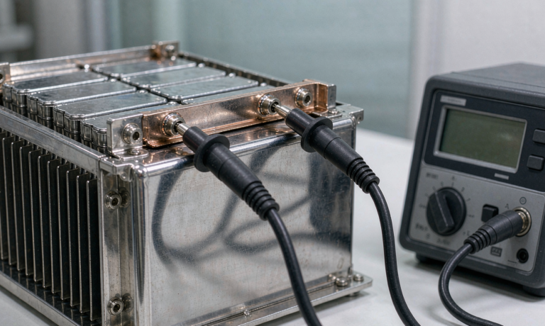
We qualify pulse resistance with a 4-wire Kelvin method at 50% state of charge and 25°C, then re-measure at 80% and 20% SoC because resistance rises as the cell empties. A pack that passes the spec at half charge but sags 25% harder at 20% is a pack that will feel weak exactly when the user is tired and wants to finish the last cut. That is the failure mode I engineer out first.
Voltage Sag vs State of Charge: the End-of-Cut Weak Knee
The single biggest “why does my battery die” complaint comes from the sag-versus-SoC curve, not from capacity. A 10S NMC pack runs 42.0V full → 36V nominal → 30V cut-off. The open-circuit voltage is only half the story; under a 90A pulse the terminal voltage is what the tool’s controller reads. Worked numbers for a 40V brushless saw pack:
- Full pack, 90A pulse: 33.0V_oc − 2.7V sag = 30.3V at terminals — comfortable margin above the 27–28V controller UVLO.
- End of charge (pack at ~33V_oc, ~10% remaining), 90A pulse: 33.0V − 2.9V sag = 30.1V — margin has collapsed to nothing.
- End of charge, a knot-induced 110A pulse: 33.0V − 3.74V = 29.3V — the controller trips, torque vanishes, the cut stalls.
This is the weak knee. The user has 10% charge left on the gauge, but the pulse resistance at that depth pushes terminal voltage under the lockout. The fix is not “more amp-hours” — it is a lower pack resistance and a cutoff tuned to the real pulse profile. I routinely specify the BMS UVLO at 2.90V/cell (29.0V pack) with a 200ms delay so a single transient pulse does not false-trip, and I size the parallel count so pulse sag stays under 8% even at 15% remaining. A well-designed custom battery solution holds torque through the last cut; a cheap one drops it.
Duty-Cycle Heat Accumulation: I²t, Not Just I²R
People model tool-pack heat as steady I²R. That is wrong for pulsed tools and it is why so many packs overheat on the second or third consecutive cut. The damaging quantity is I²t accumulated across the work session, smoothed by cell thermal mass but not erased. Consider a circular saw doing six 6-second cuts at 45A with 30-second rests:
- Per cut energy dissipated in resistance: I² × R × t = 45² × 0.03Ω × 6s ≈ 365 J per cut.
- Cell thermal mass (a 21700 is ~65g, ~0.9 J/g·K effective) absorbs the pulse as a 2–4°C rise that the 30-second rest only partially sheds.
- After six cuts with short rests, pack core temperature has climbed 12–18°C and the next cut starts from a hotter baseline — resistance is now ~8% higher, sag is worse, and the weak knee arrives earlier.
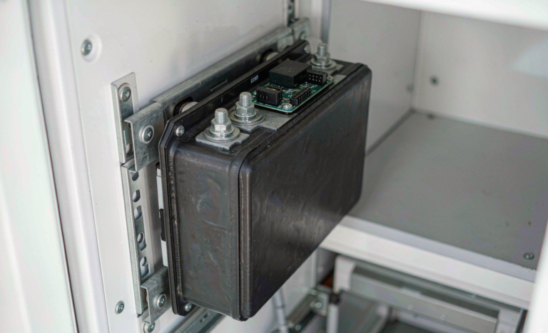
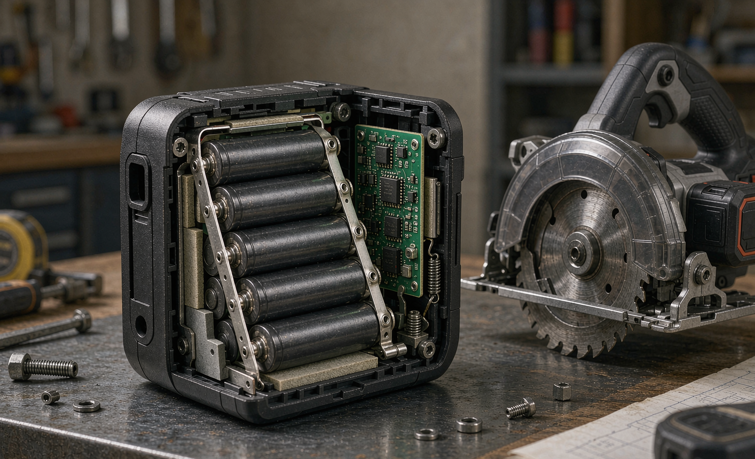
Heat is the silent killer of a lithium-ion battery in tools. Every ~10°C of sustained operating temperature roughly halves calendar life (Arrhenius), so a pack that runs at 55°C in a sealed plastic shell ages half as fast as one held at 45°C. We manage this without fans — power-tool packs are sealed — by selecting low-DCIR cells, using thermally conductive gap filler at hot spots, and shaping the enclosure for convection. I also tune the BMS to step the charge current down above 45°C, because the fastest way to cook cells is to charge a hot pack straight off the saw.
Sizing the Pack to Hold Torque at End of Charge
When an OEM asks me to beat a competitor’s saw on the same job, I start from the motor’s current profile, not the cell catalog. For a 40V-class brushless saw cutting 38mm OSB, the duty is ~45A continuous, 95A peak on resistance. My sizing contract:
- Topology: 10S3P high-rate NMC 21700 (25A cell) → pack continuous 75A, peak 2s 100A+ with margin.
- Target pack pulse resistance ≤ 30 mΩ so a 95A pulse sags ≤ 2.85V; terminal voltage stays ≥ 30.1V even at 12% SoC.
- BMS UVLO at 2.90V/cell with 200ms debounce; torque-limited, not torque-killed, near empty.
- Thermal: gap-filler at busbars + enclosure convection fins keep core under 50°C through a 10-cut back-to-back sequence.
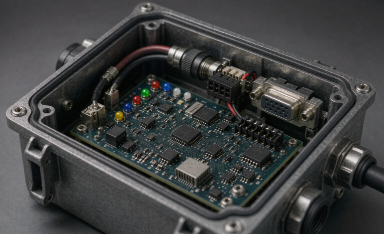
The result is a pack that delivers the same cut depth on cut #10 as on cut #1, and that still has torque when the gauge reads 12%. That is the difference a buyer feels but cannot see on a spec sheet. It is also why I tell OEMs that the BMS and the interconnect design — not the cells — are the real product. Even a drone battery pack lives or dies by the same pulse-IR discipline; the duty cycle is different but the physics is identical.
Standards and Validation for High-Drain Tool Packs
A performance pack is worthless if it cannot be certified and shipped. For power tools we validate against the same transport and safety baselines I use across every high-rate product:
- UN38.3 (T.1–T.8): altitude, thermal, vibration, shock, external short, impact, overcharge, forced discharge — the transport floor.
- IEC 62133-2: cell and pack safety for portable applications; the baseline for the BMS trip points.
- IEC 62841: the tool-side safety envelope that defines the pack’s operating limits in the field.
- UL 2054 / UL 2595: North American pack and charger-system compliance.
- FAA / EASA air-transport rules for aftermarket packs shipped with spare cells.
My validation sequence runs the pack at rated pulse current until case temperature stabilizes, then holds it through a 200-cycle pulsed duty profile while logging DCIR growth. A pack that enters at 30 mΩ and stays under 39 mΩ (under +30%) at 80% retained capacity passes. Anything that crosses the line gets the interconnect or the cell grade re-designed before it ever reaches a jobsite. Certification is a floor, not a performance promise — the jobsite is the real test.
FAQ
What is the best lithium battery for power tools?
For most professional cordless tools a high-rate NMC 18650 or 21700 cell in a well-balanced, low-resistance pack offers the best mix of energy, current capability, and weight. LFP wins on safety and cycle life but costs weight and cold-weather voltage, so it suits lower-power or stationary tool duty.
Why does my battery lose power at the end of a cut?
Voltage sag from internal resistance grows as the cell empties. At low state of charge a hard pulse can pull terminal voltage under the tool’s under-voltage lockout, cutting motor torque even though the gauge still shows charge. Lower pack resistance and a pulse-aware cutoff fix it.
Does a higher amp-hour rating stop the weak-knee problem?
Not directly. More amp-hours means more runtime, but if the parallel count and cell grade do not lower pulse resistance, the sag at end of discharge is the same. The right fix pairs enough Ah with low-resistance cells and a BMS tuned to the real pulse profile.
How hot is too hot for a power tool battery?
Sustained pack-core temperatures above ~50°C accelerate aging sharply — roughly halving life per additional 10°C. We design sealed packs to stay under 50°C through back-to-back cuts and step charge current down above 45°C to protect the cells.
Are power tool batteries and drone batteries engineered the same way?
The duty cycles differ, but the core physics is the same: low internal resistance, pulse-aware sizing, thermal management, and a BMS that protects against the real load — not the average. A good custom battery solution starts from the current profile in both cases.