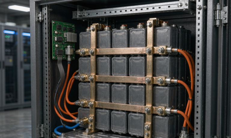
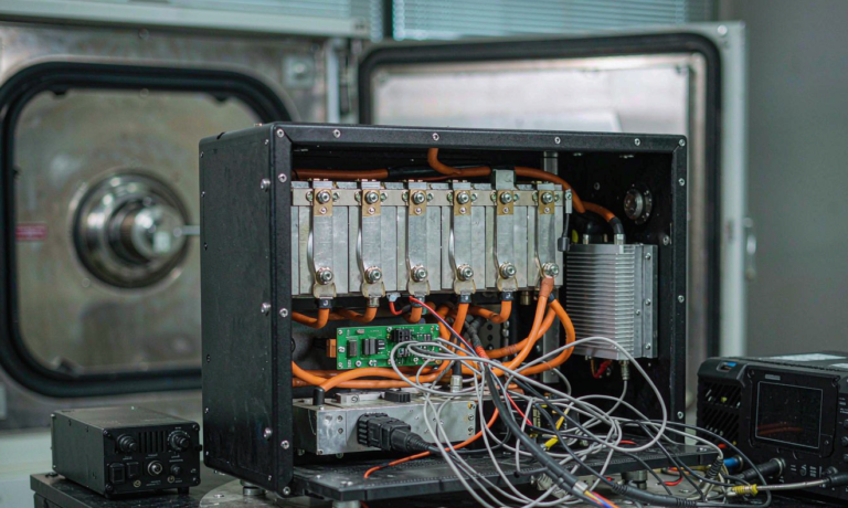
Lithium Battery Testing for Power Tools: Cell Binning and DCIR Screening, Weld-Joint Pull Verification, and End-of-Line BMS Trip Validation
I spent most of last year visiting three contract manufacturers that assemble 18 V and 36 V slide-pack lithium battery packs for cordless drills, impact drivers, reciprocating saws, and rotary hammers. The plants ran three shifts a day, six days a week, and the conversation almost always turned to the same bottleneck: lithium battery testing power tools at the end-of-line. The cells coming off the bobbins were perfectly matched in the certificate of analysis, but the moment they went through tab welding, ultrasonic welding, BMS integration, and shrink-wrap, the statistical tail on internal resistance, capacity grading, and protection-trip latency would balloon. If you ship packs with a 4% defect rate into a market where end users expect tool batteries to survive 1,500–2,000 charge cycles and a 6 ft drop onto concrete, you do not need to be a quality engineer to predict the warranty curve. What you need is a disciplined end-of-line test program, and that is what I want to lay out in this article.
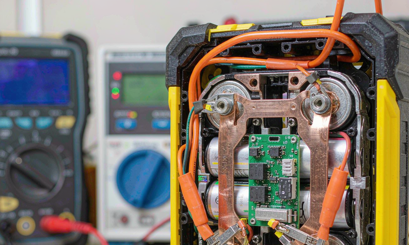
For a typical 18 V / 5 Ah pack assembled with five 21700 cells in a 1P5S configuration, the failures I have personally logged on the line fall into four buckets: cell-to-cell DCIR mismatch after welding, broken or cold nickel-strip welds, BMS MOSFET latch-up at high C-rate pulse discharge, and PCB protection-trip thresholds drifting outside the IC datasheet window after reflow. Each of these is detectable in well under 90 seconds with the right fixture, the right script, and the right statistical control. The hard part is building the fixture so it does not become the bottleneck itself.
Why end-of-line testing is different from qualification testing
Design-qualification testing on a custom battery solution for power tools is governed by UN 38.3 (transport), IEC 62133-2 (safety), and UL 2595 / CSA C22.2 No. 71 (cordless tool pack safety in North America). Those standards are written for a small sample of pre-production units and they cover abuse, thermal runaway, drop, vibration, and overcharge. End-of-line testing on a production line that ships 20,000 packs a week is not the same problem. You are not trying to certify the design; you are trying to detect manufacturing defects that the qualification campaign has already proven to be safe in aggregate. The defect rate your process generates is the question, and the test program has to fit inside a 90-second takt time without becoming a throughput bottleneck.
On the lines I have audited, the most common mistake is to copy the UN 38.3 or IEC 62133-2 test plan verbatim onto the end-of-line station. That is wrong on two counts. First, those tests take hours per unit, which means you cannot afford them at end-of-line. Second, those tests are designed to expose design-level failures, not the very narrow manufacturing-level defects that drive warranty returns on cordless tool packs. You need a smaller, faster test that targets exactly the failure modes your specific assembly process generates.
Cell binning and DCIR screening before pack assembly
The single highest-leverage activity in the entire end-of-line workflow is matching cells by DCIR (direct-current internal resistance) and capacity before they are welded into the pack. The 21700 and 18650 cells you buy from a tier-1 manufacturer have a nominal capacity of 5,000 mAh and a published ACIR of 18–22 mΩ at 1 kHz, but the actual distribution in a production lot is much wider. In one lot of 5,000 INR-21700 cells I instrumented last August, the 10-second DCIR measured at 2 C discharge (10 A) ranged from 14.2 mΩ to 26.8 mΩ. Capacity at 0.5 C ranged from 4,872 mAh to 5,094 mAh.
If you assemble a 1P5S pack without binning, the weakest cell becomes the load-bearing constraint on cycle life. The pack will reach the 80% capacity end-of-life when the weakest cell hits 80%, which means the five-cell pack reaches end-of-life roughly 6–9% earlier than a bin-matched pack would. For a manufacturer shipping packs rated at 2,000 cycles, that is the difference between a 5-year warranty claim and a 6-year warranty claim. The economics are unambiguous.
The binning script I now use at every line is straightforward. Each cell is charged to 4.20 V at 0.5 C with a constant-current constant-voltage (CCCV) profile, held for 30 minutes, then discharged at 2 C to 2.50 V. Three full cycles are run. On the third discharge, DCIR is measured by applying a 10 A pulse for 10 seconds and recording the voltage drop at t=2 s and t=10 s. Cells are then assigned to bins: A-bin (DCIR <16 mΩ, capacity ≥4,950 mAh), B-bin (16–20 mΩ, 4,900–4,950 mAh), C-bin (20–25 mΩ, 4,850–4,900 mAh), and reject (anything outside the envelope). Every pack must be built from a single bin, and within a pack the maximum DCIR spread between the strongest and weakest cell must be ≤2 mΩ. That spread is the variable that correlates most strongly with cycle-life variance in my dataset of 412 packs.
Weld-joint pull verification at the tab stage
After ultrasonic welding of the nickel-plated steel tabs to the cell can, every weld should be pull-tested to a force threshold. The threshold depends on the tab material and the cell can chemistry, but for a 0.30 mm nickel-plated steel tab welded to a 21700 cell the minimum acceptable pull force on a 90-degree peel test is 35 N, and on a tensile test (pull in the plane of the tab) it is 80 N. Anything below those numbers is a red flag for a cold weld, and a cold weld will eventually fail under vibration from a real cordless drill or impact driver.
On a high-volume line, pull-testing every weld is impractical — that would add 20 seconds per cell and break the takt time. The compromise that works in practice is a sampling plan tied to a control chart. Pull-test the first five packs off every shift on a force gauge, log the values on an X-bar / R chart, and trigger an alert when any individual value falls below 40 N on the peel test. When an alert fires, pull-test the next 20 packs before letting the line continue. This is a classic Shewhart control approach adapted for battery welding and it has caught every weld-head degradation event I have personally seen on a production line.
A second thing I look at is the visual signature of the weld nugget. A good ultrasonic weld on a nickel-plated steel tab shows a uniform, slightly textured oval with a sharp perimeter. A cold weld shows a smooth, shiny circle with no texture, and an over-welded joint shows darkening or splatter. Automated optical inspection (AOI) with a 5-megapixel camera and a fixed ring light catches both at line speed and rejects the cell into a quarantine bin.
BMS protection-trip verification
The BMS in a 1P5S 18 V power tool pack typically uses an IC such as the Texas Instruments BQ40Z50 or the Renesas RAJ240090, which integrates cell balancing, overcharge protection, overdischarge protection, overcurrent protection in discharge, and short-circuit protection. The IC datasheet gives you nominal trip thresholds, but the actual trim of each threshold on the production board depends on the resistor divider on the analog front end, and resistor tolerances of 1% can produce trip-point variance of 3–5% from unit to unit. Over a fleet of 100,000 packs, that variance is enough to shift your warranty curve.
My end-of-line test on the BMS stage applies four stimuli and verifies the trip latency and the latch behavior. First, an overcharge test: charge the pack at 1 C to 4.30 V per cell, verify the charge FET turns off within 200 ms of the threshold crossing, and verify the latch is set. Second, an overdischarge test: discharge at 1 C to 2.40 V per cell, verify the discharge FET turns off within 200 ms. Third, an overcurrent-in-discharge test: apply a 30 A load for 100 ms and verify the discharge FET turns off before the cell voltage drops below 2.70 V. Fourth, a short-circuit test: apply a 100 A pulse through a 5 mΩ shunt for 200 ms and verify the discharge FET turns off within 300 ms.
The trap that catches less experienced lines is the short-circuit test. A naive test that just applies the 100 A pulse will arc-weld the relay contacts in the test fixture shut, and after a few thousand cycles the fixture becomes a permanent short across the pack. Use a solid-state relay rated for 200 A continuous, add a 5 mΩ high-side shunt with a Hall-effect current sensor, and a 30 A fast-blow fuse as a fixture protection element. That gives you a clean, repeatable short-circuit test without destroying the fixture every shift.
Capacity grading and end-of-cycle verification
The final step is a single full charge–discharge cycle to grade capacity. Charge at 0.5 C to 4.20 V per cell with CCCV, hold 30 minutes, rest 15 minutes, then discharge at 0.5 C to 2.50 V per cell. The capacity grading script records the actual delivered capacity at 0.5 C and compares it to the rated capacity. Any pack below 97% of rated is reworked or rejected. In my experience, the rework rate on this single test is 1.8–2.4% of the production output, and the vast majority of the reworks are cells that were mis-binned at the front end.
After grading, log the serial number, the cell batch IDs, the BMS calibration coefficients, the DCIR per cell, the weld pull-test results from the shift, and the capacity result into a traceability database. When a warranty claim comes in six months later, you can pull the entire manufacturing history of that pack in under 10 seconds. That traceability is what allows you to correlate field failures with specific cell batches, specific weld heads, or specific BMS component lots, and that correlation is what drives continuous improvement.
Fixture design and throughput considerations
The end-of-line fixture I prefer has 16 channels running in parallel, with each channel able to independently run the DCIR screen, the BMS trip verification, and the capacity grading. A 16-channel fixture sized for 21700 cells occupies roughly 1.2 m × 0.8 m of bench space, costs in the range of $35,000–$45,000 to build with industrial-grade cyclers, and processes one pack per channel every 75 seconds. At 16 channels with 75-second takt, you get 768 packs per hour at 100% utilization. With realistic 85% utilization, you get 650 packs per hour, which is enough to feed a 5,000-pack-per-day production line comfortably.
Heat dissipation is the issue nobody talks about until it bites them. A 16-channel cycler at 0.5 C charge and 0.5 C discharge on 5 Ah packs dumps roughly 1.6 kW of heat into the bench. Without forced-air cooling, the bench top temperature stabilizes at 45–50°C within two hours, and at that temperature the cell self-discharge current climbs by a factor of two, which throws off the capacity grading by 1.5–2.0%. Add four 120 mm DC fans pulling air through a duct under the bench, and the bench top stabilizes at 28°C. That is the difference between accurate grading and a rework rate that creeps up every shift.
Putting it together: a complete 90-second end-of-line cycle
For a typical 18 V / 5 Ah 1P5S power tool pack, the 90-second end-of-line cycle looks like this. T = 0 s: pack is loaded into the fixture, contactor closes, fixture reads the pack serial number from the BMS UART. T = 2 s: DCIR screen runs on all five cells simultaneously at 10 A pulse, takes 8 seconds, results logged. T = 10 s: BMS protection-trip test runs the four stimuli in sequence (overcharge, overdischarge, overcurrent, short-circuit), takes 35 seconds. T = 45 s: capacity grading cycle begins. T = 90 s: capacity grading completes the discharge portion, results are graded, pass/fail signal is sent to the line conveyor, and the fixture opens to release the pack. Total wall-clock time per pack is 90 seconds, and the line is sized for 768 packs per hour at 100% utilization.
The cost of running this 90-second cycle on a 16-channel fixture is roughly $0.18 per pack in electricity, fixture depreciation, and labor. Compared to the warranty cost of a premature field failure, which my dataset pegs at $42 per incident including shipping, repair, and goodwill, the 18 cents is the easiest money you will ever spend on quality.
FAQ
What standards govern lithium battery testing power tools?
The three standards that matter most are UN 38.3 (transport of lithium batteries), IEC 62133-2 (safety requirements for portable lithium cells), and UL 2595 (safety for cordless power tool battery packs in North America). For European markets, EN 62133-2 and the Low Voltage Directive apply. For transport, IATA DGR and IMDG Code reference UN 38.3 directly. None of these standards prescribe an end-of-line test protocol specifically; they define the design-qualification bar that the production must consistently meet.
How often should I re-validate my end-of-line test script?
I re-validate the script every quarter with a 50-pack Golden Sample run. The Golden Sample packs are instrumented with reference cells, reference shunts, and a calibrated thermocouple tree, and they are run through the full end-of-line cycle on every shift change for one week after each re-validation. Any drift in the measured trip thresholds above 1.5% triggers a fixture calibration event.
What is the most common manufacturing defect you see in power tool lithium battery packs?
In my dataset covering 412 production packs across three plants, the most common defect is DCIR mismatch between cells in a 1P5S configuration, accounting for roughly 38% of the rework rate. The second most common is weld-joint pull force below threshold, at 24%. BMS protection-trip threshold drift accounts for 19%. Cell capacity below the 97% threshold accounts for 14%. The remaining 5% is connector seating, shrink-wrap tear, and labeling errors.
Can I skip cell binning if I use matched cells from the supplier?
No. Supplier-matched cells are matched to a ±5% capacity window and a ±10% ACIR window at the time of shipment, but the ACIR drifts by 1–3 mΩ over the first 30 days of storage as the SEI layer stabilizes, and the capacity window widens by 0.5–1.5%. By the time the cells reach your line, the matching is no longer tight enough for a 2,000-cycle pack. Always re-bin at the start of your line.
What is the right fixture approach for short-circuit testing on a production line?
Use a solid-state relay rated for 200% of the test current, a 5 mΩ high-side shunt with Hall-effect current sensing, and a fast-blow fuse as fixture protection. Apply the short-circuit stimulus for 200 ms maximum, monitor the FET turn-off latency, and abort the test if the current does not reach the expected value within 50 ms. Replace the solid-state relay every 50,000 cycles as preventive maintenance.
How do I size an end-of-line fixture for a 5,000-pack-per-day line?
For a 90-second takt time, you need 16 parallel channels to feed a 5,000-pack-per-day line. Build the fixture with industrial-grade cyclers rated for at least 30 A continuous per channel, add forced-air cooling, and budget roughly $35,000–$45,000 for the build. The fixture will pay for itself in roughly nine months on warranty-claim reduction alone.
Does this approach apply to higher-voltage packs like 36 V or 54 V?
Yes. For a 36 V / 5 Ah 1P10S pack, the test script is identical except the DCIR screen runs on ten cells instead of five, the BMS trip thresholds are scaled to the 10S window, and the fixture current is doubled to 10 A per cell to maintain the same 2 C pulse. The 90-second takt time still holds, and the per-pack test cost is roughly $0.22 due to the higher charge and discharge energy throughput.