Semi-Solid State Battery Tab Welding and Joint Design
After cell chemistry, nothing limits what a semi-solid state battery can deliver like its tab joints. I have watched packs built from excellent cells fail a 200 A discharge test because one weld added tens of micro-ohms where heat had nowhere to go; the joint was eating an engineering margin measured in single square centimetres. Semi-solid state battery tab welding deserves the same attention as the coating line, because semi-solid cells stack fewer, thicker electrodes, which changes how current funnels out. This article covers process selection, the copper-to-aluminium trap, stack-pressure fatigue, and the tests that predict field performance.
Why the Tab Joint Sets the Current Ceiling of a Semi-Solid Cell
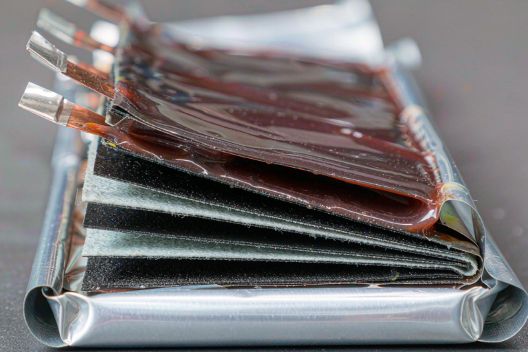
A typical positive tab is a bundle of about twenty layers of 12 um aluminium foil, 40 mm wide, welded over a 40 mm footprint. The cross-section is roughly 9.6 square millimetres, and with aluminium resistivity near 2.65 x 10^-8 ohm-metres, a 40 mm run of that bundle is about 110 micro-ohms. At 150 A that is 2.5 watts spread over 40 mm of tab. A mediocre weld can add another 100 micro-ohms, which puts 2.25 additional watts into a spot smaller than one square centimetre. Inside a sealed pouch, that heat has nowhere to go but through the seal area.
Semi-solid electrodes push this harder: coatings run 100 to 200 um thick, so a cell reaches capacity in fewer layers and each foil carries more current, with less parallel path area at the shoulder. The joint is therefore a larger share of total path resistance than in a high-layer-count wound cell. Our rule is that the complete joint, foil-to-foil plus tab-to-terminal, must beat an equivalent length of foil on resistance, or the weld becomes the hottest point of the cell.
There is also a local temperature limit. We design joints to stay under 10 to 15 kelvin of rise relative to the cell body at rated current. Push past that and the aluminium anneals and loses strength near the weld, while heat conducts into the pouch seal and shortens seal life. Neither shows up on a capacity test in week one; both surface as a field return in year two.
Choosing the Joining Process: Ultrasonic, Laser, or Resistance
Three processes dominate tab joining, and each interacts differently with a semi-solid stack.
Ultrasonic metal welding
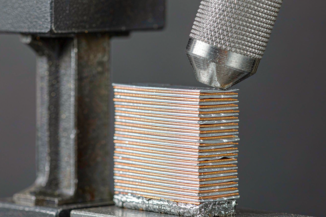
Ultrasonic welding is the default for foil-to-tab bundles. A 20 kHz system oscillating at 15 to 30 um amplitude presses a knurled horn onto the stack at roughly 0.3 to 0.6 megapascals while delivering 400 to 800 joules over 0.3 to 0.8 seconds. Because the process is solid state, peak interface temperature stays below roughly 250 to 350 degrees Celsius and no melt pool forms, so it works through oxide films and keeps heat away from anything fragile nearby. The key quality indicator is collapse, the thickness reduction after welding, which we target at 20 to 40 percent of the unbonded stack height. Under-collapse leaves unbonded layers that oxidise later; over-collapse thins the foils below 60 percent of original thickness and seeds cracks.
Laser welding
Laser welding suits tab-to-busbar joints where the geometry is a single solid tab, not a foil bundle. The catch is optical absorption. Aluminium reflects most of a 1070 nm fibre laser until it melts, and copper is worse: solid copper absorbs only a few percent at that wavelength, which is why green 532 nm and blue 450 nm sources, or high-power beams with beam oscillation to force a stable keyhole, have become popular for copper. A molten pool brings spatter and porosity risk, so we insist on 10 to 20 litres per minute of shield gas and a closed-loop weld monitor. For semi-solid cells with lithium-metal or high-silicon anodes, I keep lasers away unless the beam path is shielded, because spatter near a lithium surface is a safety event, not a quality defect.
Resistance welding
Resistance spot welding suits thin nickel or aluminium connections in small packs but not the main current path of a semi-solid cell: copper pulls heat from the interface, demanding very high current and yielding inconsistent nuggets across a multi-foil bundle. We reserve it for sensing leads, never the tab bundle.
Semi-solid specific complications
Semi-solid stacks add three wrinkles. First, thick semi-dry coatings shed particles near the tab clearance zone that contaminate the horn knurl, so weld head cleaning is scheduled by point count, not calendar. Second, if the anode is lithium metal, its melting point is only 180 degrees Celsius; welding energy must land far from the lithium edge and a heat-sink clamp between the weld and the active area is standard practice for us. Third, semi-solid assembly happens in a dry room at dew points of -40 degrees Celsius or lower, so any weld rework costs a full cycle back through the dry side and first-pass yield matters economically.
Copper-to-Aluminium Transitions and the Intermetallic Trap
Copper and aluminium must meet somewhere in every pack. Fusion welding copper directly to aluminium produces brittle intermetallic compounds such as CuAl2 and Cu9Al4, plus a shrinkage-cracked weld. A joint with intermetallic layers thicker than two to three micrometres loses shear strength and gains resistance. The growth of these layers follows parabolic kinetics and roughly doubles in rate for every 20 to 25 kelvin of temperature increase, so a joint held hot can degrade measurably within hundreds of hours even when it passed every initial test.
The proven solutions are all about staying solid state or inserting a barrier. Ultrasonic welding keeps intermetallic formation under about one micrometre because the interface never melts and the process time is under a second. Nickel plating, typically 2 to 5 um, on the copper tab buys corrosion resistance and a friendlier surface for bonding. For busbar-level transitions we use roll-bonded or explosion-bonded copper-aluminium strips, where the intermetallic is formed and controlled once in a specialist factory rather than at every joint. Our design rule is simple: one transition at the copper-aluminium interface, a maximum operating temperature around 100 degrees Celsius, and never a fusion weld across the two metals.
Tab Geometry, Stack Pressure, and Fatigue at the Shoulder
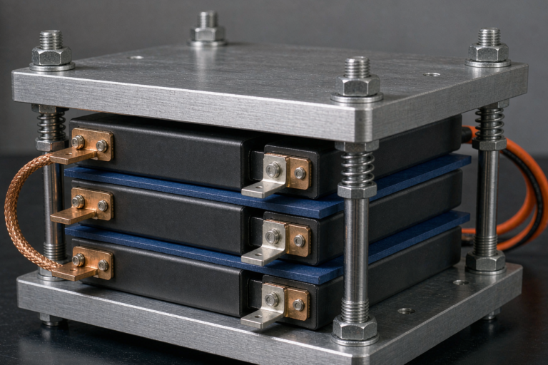
A tab weld that passes every static test can still fail in the field because of how the cell breathes. Semi-solid cells with lithium-metal or silicon-blended anodes expand 5 to 15 percent through the stack, and even conventional graphite blends move 1 to 2 percent. Under module stack pressure of 0.05 to 0.3 megapascals, that expansion cycles the tab root thousands of times over the cell life. A tab that exits the seal in a straight line concentrates all of that bending at one point. We form a stress-relief bend or S-loop into every tab so the cycling is distributed, and we keep the weld footprint at least 3 to 5 mm away from the seal edge.
The pouch seal itself deserves equal care. Ultrasonic welding pumps heat into everything within a few millimetres, and polypropylene sealants soften well below the temperature the foil interface reaches. We always fit a heat-sink clamp between the welding zone and the seal during production. It is a two-dollar fixture that prevents a defect you will not see until a late leak test, or in the field.
How We Verify Tab Joints Before They Ship
No single test predicts joint quality, so we use four in combination.
- Tensile shear. For the twenty-layer, 40 mm aluminium bundle described earlier, base-metal failure force lands around 430 to 860 newtons depending on foil temper. Our acceptance line is joint failure at or above 60 percent of base-metal failure, with the failure mode recorded.
- Peel. A T-peel on outer foil layers separates cohesive welds from cosmetic ones: foil tearing through the bond line passes; clean interface separation fails even if the force number looks acceptable.
- Metallographic cross-section. Sections show unbonded layers, voids, and over-thinning; we reject joints where local foil thickness drops below about 60 to 70 percent of nominal or more than one layer in twenty is unbonded.
- Electrical. Four-wire resistance on the finished joint, accepted at 100 micro-ohms or below for this bundle size, or within 1.2 to 1.5 times the parent tab. On sample cells we also run rated current to thermal steady state and confirm the joint rises no more than 10 kelvin above the cell body.
For test methods we lean on ISO 14273 and ISO 14324 shear coupons, which adapt well to ultrasonic joints. No single international standard governs ultrasonic metal welding of battery tabs, so every serious manufacturer runs an internal specification for parameters, coupon geometry, and thresholds. UN 38.3 and IEC 62619 will eventually expose a bad joint design, but only after thousands of cells are built, which is the wrong time to learn.
Holding the Weld Window on the Production Line
A weld window is only useful if the machine cannot silently drift out of it. Modern ultrasonic welders record energy, power, time, force, and collapse depth for every point, and we alarm at plus or minus 5 to 10 percent of the validated setpoints. A trend line matters more than any single alarm: rising energy demand at constant settings usually means the horn knurl is worn or the surfaces are contaminated.
Horn and anvil management is the most neglected control. A pyramid-toothed horn lasts roughly 50,000 to 100,000 points on aluminium before the texture flattens, slip increases, and bond quality falls even though the monitor shows normal energy. We count points per tool and re-texture or replace on schedule. Surface preparation has a clock on it too: a cleaned aluminium surface re-grows its oxide film within a day or two, so parts must be welded within 24 to 48 hours of cleaning.
Finally, traceability closes the loop. Every weld parameter record is bound to the cell serial number, so if a batch shows rising DCIR months later we can pull the exact weld log instead of guessing. That habit separates a line that holds quality for years from one that drifts until a customer finds it.
Frequently Asked Questions
Can you laser weld copper tabs in a semi-solid state battery?
Yes, but only with the right optics. Solid copper absorbs only a few percent of 1070 nm laser light, so green 532 nm or blue 450 nm sources, or beam oscillation on a high-power fibre laser, are used instead. Expect to manage spatter and porosity with shield gas and weld monitoring, and keep the beam path away from lithium-metal anodes.
Why is welding copper directly to aluminium a problem?
Fusion welding forms brittle intermetallics such as CuAl2 and Cu9Al4, which crack on cooling, raise resistance, and keep growing with time and temperature. Use solid-state ultrasonic welding, a plated barrier, or a factory-bonded transition strip instead.
How many foil layers can ultrasonic welding join in one tab?
Production systems routinely weld 20 to 60 layers of 8 to 15 um aluminium foil and 20 to 40 layers of copper foil in a single impression. The limit is less about layer count than about total stack height and the collapse window; beyond roughly 2 mm of unbonded height, energy distribution becomes uneven and the outer layers bond poorly.
What does a failing tab weld look like in the field?
Rising internal resistance and localised heating at one terminal, sometimes with pouch discolouration near the tab root. The failure usually starts as an oxidising unbonded outer foil layer, or as fatigue cracking at a straight, unsupported tab shoulder after thousands of expansion cycles.
Does stack pressure affect tab weld life?
Indirectly, and significantly. Stack expansion of 5 to 15 percent cyclically bends the tab root under module pressure. Stress-relief bends, a weld footprint away from the seal, and joints verified for fatigue rather than static shear alone are what hold up.
How do you measure the resistance of a finished tab joint?
With a four-wire measurement across the joint at a defined distance. Acceptance is typically 100 micro-ohms or less for a mid-size bundle, or within 1.2 to 1.5 times the parent value, followed by a rated-current thermal check on sample cells.
Further Reading
References