
Drone Battery Reliability for Mapping UAVs: FMEDA,
I have spent the better part of a decade building packs for survey aircraft, and the hardest lesson I learned did not come from a cell datasheet. It came from a corridor mapping job in Guangdong where a perfectly healthy pack — 94% state of health, balanced within 8 mV, fewer than 60 cycles — put an aircraft down in a rice field. The cells were fine. A single thermistor lead had work-hardened at the crimp, opened intermittently, and the battery management system did exactly what a poorly architected BMS does: it read an implausible temperature and latched a protective shutdown mid-transect. Nothing on the cell level failed. The architecture failed.
That flight changed how I approach every drone battery programme. Reliability for a mapping UAV is not a cell-selection problem. It is a systems-safety problem, and it responds to the same tools aerospace electronics teams have used for thirty years: FMEDA, diagnostic coverage, reliability block diagrams, and deliberate redundancy. This article is the working method my team uses to move a survey drone lithium battery from “good cells in a nice case” to a pack with a quantified probability of completing the mission.
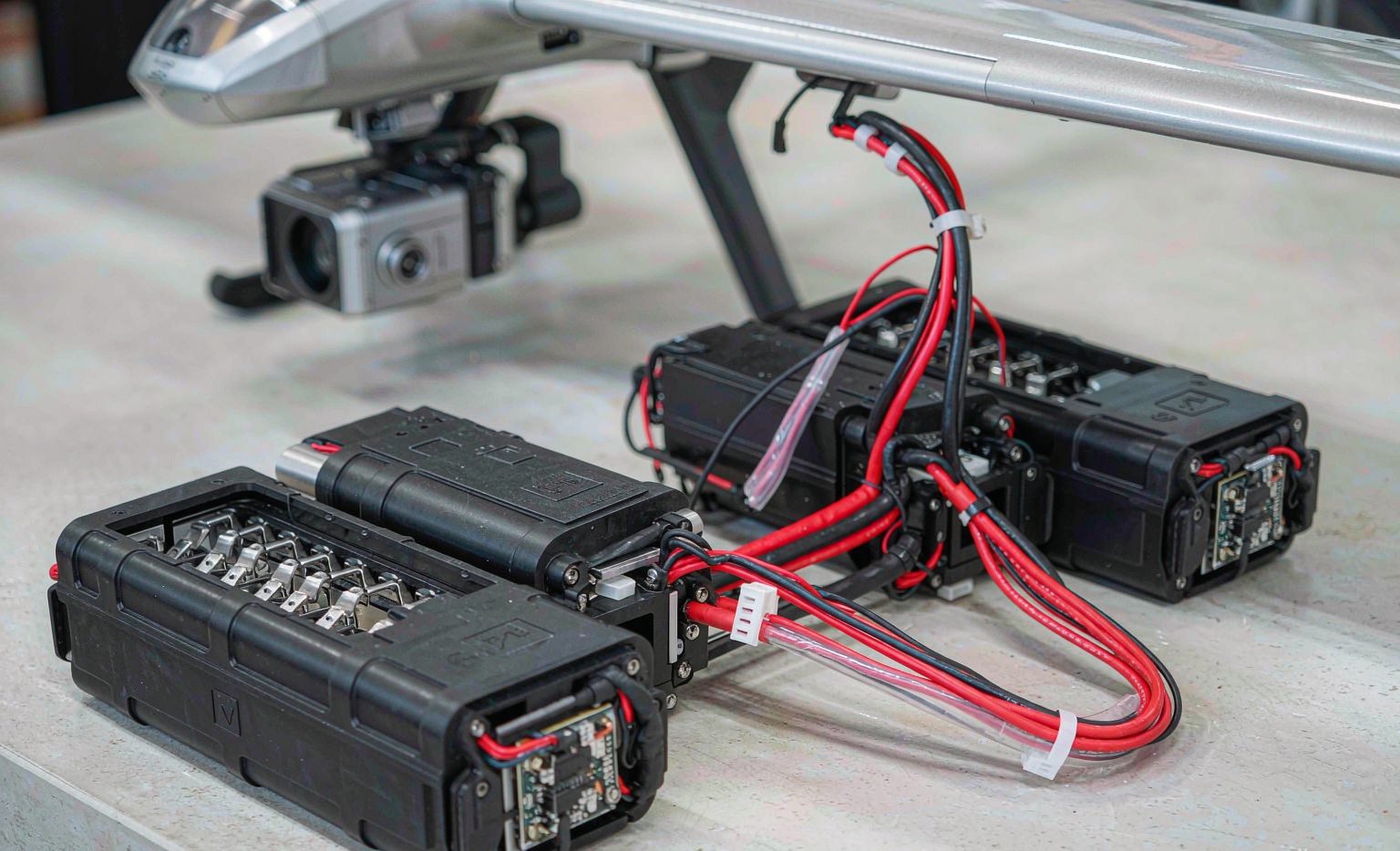
Why Mapping UAVs Punish Architecture Faults More Than Any Other Mission
A racing pack lives for 90 seconds at 40C and nobody dies if it sags. A mapping UAV is the opposite duty cycle and the opposite risk profile. The pack discharges at 1–2C for 35 to 60 minutes, holds a near-constant load while the aircraft flies rigid grid lines, and cannot tolerate an interruption because the photogrammetric block is only valid if overlap is continuous. A dropout at line 14 of 20 does not cost you 30% of the data; it can cost you the entire survey, because re-flying a partial block under different sun angle and cloud cover often fails the bundle adjustment.
Three consequences follow directly, and they drive everything else in this article:
- Nuisance trips are mission failures. A false protective shutdown is functionally identical to a real cell failure from the customer’s point of view. Most survey-fleet field returns I have analysed were diagnostic false positives, not cell defects.
- Latent faults accumulate quietly. Cruise at 1.5C generates almost no thermal or voltage signature, so a degrading interconnect or a drifting sensor produces no symptom until it is a hard failure.
- The failure is remote. Corridor and cadastral work happens 40 minutes from a road. There is no abort-to-pad option; the pack has to degrade gracefully, not stop.
So the design objective is not maximum energy density. It is maximum probability of uninterrupted power delivery for the mission duration, including under single-fault conditions. That is a reliability requirement, and it has to be written as a number before anything gets designed.
Start With a Reliability Block Diagram, Not a Cell Choice
Before I select a single component, I draw the reliability block diagram (RBD) for the energy system and allocate a failure budget across it. For a typical fixed-wing mapping platform with a 45-minute mission, a realistic customer requirement is a mission failure probability below 1×10⁻⁴ per flight attributable to the battery subsystem — roughly one battery-caused abort per 10,000 flights.
Allocating that budget is where the surprises live. Here is a representative allocation from a 6S2P survey pack programme, expressed as failures per million flight hours (FIT-equivalent, mission-normalised):
- Cells (12 in the assembly), series-critical: ~18% of the budget. Modern high-quality NMC pouch cells are the least likely thing to fail in a well-managed pack.
- Welded and bolted interconnects, tabs and busbars: ~24%. Mechanical fatigue under vibration is the single largest hardware contributor.
- Sensing chain — thermistors, voltage taps, harness, connectors: ~31%. This is the dominant term, and it is almost entirely a wiring and strain-relief problem.
- BMS electronics (AFE, MCU, FET/contactor drive): ~19%. Predictable via part-count methods such as IEC 62380 or MIL-HDBK-217F notice 2.
- Output connector and aircraft interface: ~8%. Underestimated by nearly everyone, because contact resistance growth is invisible until it is thermal.
Notice where the money should go. Roughly 55% of the mission-failure budget sits in sensing and interconnect — the parts of a drone battery that cost cents and get the least engineering attention. Teams chasing an extra 4% in cell energy density while crimping thermistor leads by hand are optimising the smallest term in their own budget.
FMEDA: Turning “It Might Fail” Into a Diagnostic Coverage Number
Failure Modes, Effects and Diagnostic Analysis (FMEDA) is the discipline that separates a serious reliability programme from a spreadsheet of good intentions. Where a classic FMEA asks “what fails and what happens,” FMEDA adds the question that actually matters for a battery in flight: can the BMS detect this failure, and what does it do about it?
Every failure mode gets sorted into four buckets:
- Safe detected (SD): the fault occurs, diagnostics catch it, the system enters a defined safe state — ideally a degraded-but-flying state.
- Safe undetected (SU): the fault occurs and has no mission effect, detected or not.
- Dangerous detected (DD): a mission-critical fault that diagnostics catch in time to act.
- Dangerous undetected (DU): the killer category. The fault is mission-critical and invisible until it manifests. Every DU item on the sheet is an unannounced abort waiting for a schedule.
Diagnostic coverage is then simply DC = λDD / (λDD + λDU). On a first-pass FMEDA of a conventional survey pack, my teams typically measure 62–71% coverage. After two design iterations targeted specifically at the DU rows, we reach 90–94%. That improvement is worth more mission availability than any cell upgrade available on the market, and it is achieved almost entirely in firmware and harness design.
The three DU rows that appear on nearly every first-pass FMEDA I have run:
- Intermittent open on a temperature or voltage sense lead. Reads as a plausible value until it does not. Undetectable without plausibility cross-checking.
- Slow-developing internal short circuit (ISC) in a single cell. Produces a self-discharge signature of a few millivolts per week — invisible to any single-flight check.
- Interconnect resistance growth from vibration fatigue. Adds a few hundred microohms per hundred flight hours; at 1.5C cruise it generates no detectable heat until it is severe.
Closing the Coverage Gap: Three Diagnostics That Earn Their Place
Coverage is not bought with more alarms. It is bought with diagnostics that use physics the failure cannot fake. Three that I now specify on every survey-grade drone battery:
Sensor plausibility cross-checking. Each thermistor is validated against its neighbours and against a thermal model driven by measured current. If cell 3 reports a 9°C step change while cells 2 and 4 move less than 0.4°C and pack current is steady, the sensor is wrong, not the cell. The BMS flags a sensor fault, falls back to the modelled value, and — critically — keeps flying while telemetry warns the operator. That single rule converted my worst DU row into a DD row and eliminated the entire class of failure that put the aircraft in that rice field.
Rest-window self-discharge trending. The pack logs open-circuit voltage at the start and end of every storage interval longer than 12 hours, temperature-compensated. A cell drifting more than 1.5–2 mV per day relative to its siblings gets quarantined for teardown. In our field data this catches developing ISC roughly 25 to 40 flight hours before it becomes a hard fault — the difference between a scheduled cell replacement and a lost survey day.
In-flight DC resistance estimation. Every current transient from a throttle step or a turn is a free resistance measurement. Computing ΔV/ΔI per cell group across the flight and trending it flight-over-flight exposes interconnect degradation long before thermal symptoms appear. A 15% rise in group DCR against the pack’s own commissioning baseline is our maintenance trigger.
None of these requires exotic hardware. All three require that the pack was designed as an instrumented system from the start, which is exactly what a serious drone battery manufacturer should be delivering to a survey operator.
Redundant Architecture: When One Pack Is Structurally Not Enough
Diagnostics tell you a fault occurred. Redundancy is what lets the aircraft finish the transect anyway. For mission-critical mapping work — particularly BVLOS corridor survey where an abort means a recovery operation, not a walk — a dual-pack architecture is the only honest answer to a single-point failure in the energy path.
The implementation details matter more than the concept:
- ORing, not hard paralleling. Two packs bolted in parallel share a fault. Each pack feeds the bus through an ideal-diode controller driving back-to-back MOSFETs, so a pack that develops a low-impedance internal fault is isolated in microseconds instead of being fed by its healthy partner.
- Bounded state-of-charge divergence at connect. We gate parallel connection on a maximum pack-to-pack ΔV (typically 0.15 V per series element) and use a pre-charge path to equalise before the main FETs close. Skipping this step is how people weld contactors and then discover their FMEDA never covered a shorted-FET failure mode.
- Independent, non-identical sensing. Redundancy defeated by a common-cause fault is theatre. Separate harness routes, separate connectors, separate AFE supply rails — and ideally a different firmware plausibility path — so that one crushed loom cannot blind both packs.
- Honest derating. A dual-pack system sized so that one pack alone cannot complete the mission is not redundant, it is heavy. We size for single-pack continuation at reduced airspeed and a defined return leg, and we tell the customer explicitly what that reserve buys in minutes.
This costs mass: on a 15 kg survey platform we typically pay 6–9% of gross weight for a genuinely fault-tolerant energy system. Where the day rate exceeds the hardware cost, that trade closes on a single avoided re-fly.
Safe States That Keep the Aircraft Flying
The most common architectural mistake I see in a drone lithium battery is a BMS with exactly one response to every abnormal reading: open the FETs. On a multirotor at 120 m, opening the FETs is not a safe state. It is a crash.
A survey pack needs a graduated response ladder, and it needs to be written into the requirements document before firmware exists:
- Level 1 — annunciate. Sensor implausibility, mild imbalance, DCR trend excursion: telemetry warning, flight continues, event logged for maintenance.
- Level 2 — limit. Genuine cell voltage or temperature excursion: reduce allowable current, request the flight controller shorten the mission and return, never interrupt power.
- Level 3 — isolate the faulty branch only. In a redundant system, drop the failed pack and continue on the healthy one at derated power.
- Level 4 — hard disconnect. Reserved exclusively for conditions where continued discharge is a thermal-propagation hazard: confirmed multi-sensor over-temperature, or detected cell venting.
Latent-fault management belongs here too. Diagnostics that only run at power-up cannot be trusted for a 50-minute flight, so plausibility checks, watchdog validation and FET-drive integrity tests run on a periodic in-flight schedule — typically once per second for the fast paths and once per minute for the slow trends.
Validation: Fault Injection Is the Only Proof That Counts
An FMEDA is a claim. Fault injection is evidence. Our qualification programme for a survey-grade pack runs three layers, and I will not sign a release without all three:
Layer 1 — regulatory and abuse baseline. UN 38.3 tests T.1 through T.8 for transport, and IEC 62133-2 for the cell and pack safety envelope. These are entry conditions, not reliability evidence — they prove the pack is not dangerous, not that it is dependable. Vibration and shock (T.3, T.4) do double duty as an early screen on the interconnect and harness fatigue modes that dominate my failure budget.
Layer 2 — environmental life on the real duty cycle. Cycling at the actual mapping profile (1–2C constant discharge, field charge rates, the ambient range the customer flies in) with temperature cycling superimposed. A pack qualified only at 25°C on a bench profile tells you nothing about a 42°C summer corridor job.
Layer 3 — deliberate fault injection against every FMEDA row. We physically open thermistor leads mid-discharge, inject offsets into voltage taps, add calibrated series resistance to simulate interconnect degradation, short a redundant branch, and force FET-drive failures. Every injected fault must produce the documented detection and the documented safe state within the documented time. Any row that does not respond as written is a coverage claim we delete from the sheet.
The traceability structure follows ARP4761-style safety assessment logic, which matters when an operator defends a BVLOS case: a SORA submission pointing to quantified diagnostic coverage and demonstrated fault-injection results is materially stronger than one asserting “reliable batteries.” FAA Part 107 waiver and EASA specific-category reviewers respond to evidence, and this is the evidence.
What This Means When You Specify a Pack
If you operate mapping UAVs commercially, the useful questions for a supplier are not about mAh or C-rating. Ask for the FMEDA, the measured diagnostic coverage figure, and the dangerous-undetected rows they could not close. Ask what the pack does when a single thermistor opens at minute 30 of a 45-minute flight, and ask for the fault-injection log that proves it.
When we build a custom battery solution for a survey fleet, that documentation set ships with the hardware, because it decides whether the fleet flies on schedule. Cell chemistry sets the ceiling on what a lithium battery can do; architecture, diagnostics and validation decide how much of that ceiling the operator actually gets on the twelve-hundredth flight, in the field, with nobody watching.
Frequently Asked Questions
Is a redundant dual-pack architecture worth the weight penalty on a mapping UAV?
It depends on the cost of an abort, not the cost of the hardware. For photogrammetric blocks where a mid-mission dropout invalidates the whole survey, or for BVLOS corridor work where recovery is expensive, the 6–9% gross-weight penalty typically pays for itself with one avoided re-fly. For short visual-line-of-sight jobs over accessible ground, a single well-instrumented pack with high diagnostic coverage is usually the better engineering trade.
What diagnostic coverage should I expect from a professional survey pack?
A conventional pack with basic over-voltage, under-voltage and over-temperature protection measures somewhere in the low-to-mid 60% range on a rigorous FMEDA. With sensor plausibility cross-checking, self-discharge trending and in-flight DCR estimation, 90–94% is achievable. Be suspicious of any supplier quoting a coverage number without an FMEDA and fault-injection results behind it.
Why does the sensing harness dominate the failure budget instead of the cells?
Because cells are manufactured and screened in the millions under tight process control, while sense leads are thin conductors carrying no useful current through a high-vibration environment, frequently terminated by hand. Vibration fatigue at crimps and strain reliefs, plus connector contact degradation, produce far more field events than cell defects in any fleet dataset I have analysed.
Can I retrofit better diagnostics onto packs I already own?
Partially. Rest-window self-discharge trending can often be implemented in ground software alone if the BMS logs per-cell open-circuit voltage — the highest-value retrofit available. Plausibility cross-checking and in-flight DCR estimation usually need BMS firmware access. Harness and interconnect robustness cannot be retrofitted at all; it is set at build time, which is why it belongs in the specification.
Do UN 38.3 and IEC 62133-2 certification mean a pack is reliable?
No, and conflating the two causes real problems. Those standards demonstrate the pack is safe to transport and does not present an unreasonable hazard under defined abuse. Neither evaluates whether the pack will deliver uninterrupted power for 45 minutes on the twelve-hundredth flight. Reliability requires life testing on your actual duty cycle plus quantified diagnostic coverage, and those are separate deliverables from the safety certificates.





