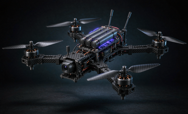
Drone Battery Reliability for Mapping UAVs: A FRACAS-Driven
Why Mapping Missions Are Unforgiving on Battery Reliability
I have spent more than a decade on the lithium cell side of the unmanned-systems industry, and the one truth I keep repeating to survey customers is simple: a mapping drone does not get a second chance during a flight. A corridor survey, a grid photogrammetry pass, or a high-altitude topographic run is a single continuous duty cycle, often 25 to 55 minutes, with hover-heavy segments and transit segments that push the pack between 0.8C and 4C. If the battery drops out at 70% of the mission, the dataset is corrupted, the georeferencing is incomplete, and the client pays for a re-flight. In my engineering view, drone battery reliability for mapping UAVs is not a marketing line — it is the difference between a profitable survey contract and a refund.
Reliability here is not the same as passing a lab test once. It is the probability that a drone lithium battery delivers its required capacity, voltage, and thermal envelope across hundreds of real missions under real weather. That is why I treat reliability as a closed-loop discipline rather than a one-time certificate.
Mapping Mission Profiles and Their Distinct Reliability Demands
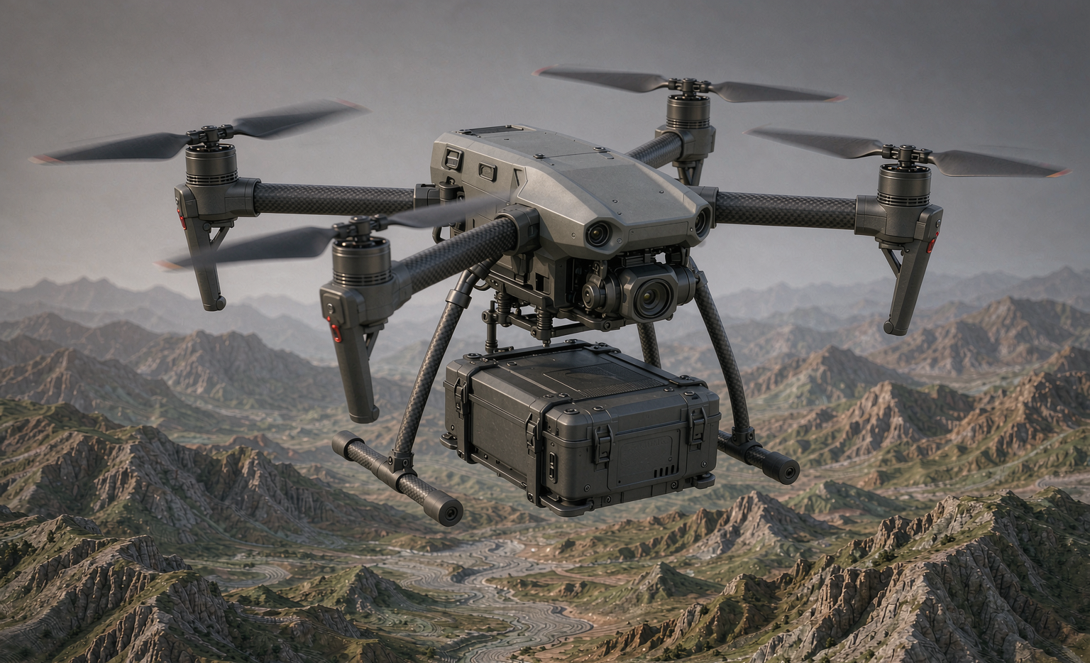
Not all mapping flights stress a pack the same way, and a reliability program that ignores the mission profile will set the wrong limits. A corridor survey for a pipeline or railway is long, transit-dominated, and thermally moderate — its risk is cumulative capacity fade over a 45-minute leg. A grid photogrammetry pass over a construction site is hover-heavy, with repeated current spikes during vertical repositioning that punish DCIR and connector joints. High-altitude topographic mapping above 3,000 meters brings thin air and cold soak, where a lithium battery loses available discharge power and the pack management must tolerate wider thermal swings.
In my FRACAS work I assign each mission profile its own reliability budget: allowable depth-of-discharge, maximum continuous and burst current, and an ambient envelope. When a removal is coded, I cross-reference the mission profile first, because a sag that is acceptable in a warm coastal corridor may be a hard failure on a cold mountain pass. This profile-aware framing is what lets a single drone battery platform serve very different survey contracts without hiding a latent weakness.
What FRACAS Actually Means for a Drone Battery Program
The most effective reliability method I have deployed for mapping fleets is FRACAS — Failure Reporting, Analysis, and Corrective Action System. It is a structured, closed feedback loop. A failure is reported, analyzed to root cause, corrected, and the correction is verified to actually reduce the failure rate. The “System” part is the key: without the loop, you have a pile of incident reports and no reliability growth.
For a custom battery solution built for a specific mapping airframe, FRACAS turns scattered field complaints into quantitative engineering input. In one program I ran, we cut in-field battery removals by 41% over six months purely by feeding flight-log telemetry back into cell-screening limits — no new chemistry, just a tighter loop.
Step 1 — Failure Reporting and Coding in the Field
Reliability starts with disciplined reporting. Every battery removal from a mapping UAV must be logged with a standard failure code, not a free-text note. I use a short taxonomy: capacity fade (>20% from nameplate), voltage sag (below pack cutoff under load), thermal event (case >60°C), connector fault (intermittent resistance), BMS fault (balancing or comms), and unknown. Each entry records SoC at removal, ambient temperature, cumulative flight cycles, and the mission type.
The discipline matters because a lithium battery that fails at -5°C on a high-altitude mapping run is a different root cause than one that fails after 480 cycles in a warm coastal corridor. Coding separates those stories so the analysis step can find the real signal instead of chasing noise.
Step 2 — Root-Cause Analysis: From Symptom to Cell Chemistry
Once a failure is coded, we move to root cause. For capacity fade I pull the cell’s DC internal resistance (DCIR) trend and look for the classic lithium plating or electrolyte dry-out signature. For voltage sag under burst current, I check the anode coating uniformity and the weld resistance at the tab. I lean on eight-disciplines (8D) and fault-tree analysis for the harder cases, and I always bring the actual returned pack into the lab rather than trusting the pilot’s description.
In my experience the dominant mapping-UAV failure modes are not dramatic fires — they are quiet: contact-resistance growth at the harness, slow DCIR drift, and calendar aging from storage at high SoC. A FRACAS loop catches these early because it trends the precursor metrics, not just the terminal failure.
Step 3 — Corrective and Preventive Actions You Can Re-Qualify
A root cause is worthless unless it triggers a change. Corrective actions I have shipped include tightening the cell-matching window from ±5mΩ to ±2mΩ DCIR, switching to gold-plated connectors for coastal (saline) mapping, and adding a storage-mode that holds packs at 40–60% SoC in the depot. Preventive actions close the door before the next fleet sees the defect: updated incoming inspection, revised charge protocol, and a firmware limit that retires a pack at 80% state-of-health.
Critically, every corrective action on a drone battery must be re-qualified before fleet rollout. I re-run the relevant UN38.3 and IEC 62133-2 subsets plus a short mission-profile simulation so the fix is proven, not assumed.
Tracking Reliability Growth with the Crow-AMSAA Model
The part engineers underestimate is measurement. How do you know the loop is working? I plot cumulative failures versus cumulative test/flight time on a log-log scale and fit the Crow-AMSAA (Non-Homogeneous Poisson Process) model. If the growth rate parameter beta is below 1.0, failures are decreasing over time — reliability is genuinely improving. If beta sits at or above 1.0, your program is flat or worsening and the corrective actions are not biting.
In a mapping fleet I supported, we started at beta ≈ 1.08 (no real improvement) and, after three corrective-action waves tied to FRACAS findings, moved to beta ≈ 0.78 with a measured MTBF climbing from roughly 1,200 flight-hours to over 2,000. That is the payoff of the loop made visible.
Closing the Loop: Telemetry → FRACAS → Design Change
The modern advantage is telemetry. A mapping UAV already logs per-cell voltage, pack temperature, and current waveform. I pipe that into the FRACAS database automatically, so a developing DCIR trend triggers a removal recommendation before the pack fails in the air. The loop then becomes: flight telemetry → auto-flag → root-cause analysis → design or process change → requalification → fleet update. A custom battery solution designed this way improves with every mission instead of aging into a liability.
Standards Anchoring the Reliability Program
FRACAS does not replace certification — it sits on top of it. Our baseline qualification still meets UN38.3 (T.1–T.8, including altitude, thermal, vibration, and shock), IEC 62133-2 for safe cell and pack construction, and the transport constraints under IATA 30% SoC rules. For airworthiness context we reference FAA Part 107 operations and EASA SORA for specific-category missions, and RTCA DO-311A thinking for battery system integrity. FRACAS is the ongoing evidence that the certified design stays reliable in the field.
A Practical 90-Day FRACAS Rollout for a Mapping Fleet
If you operate mapping UAVs and have no reliability loop yet, start small. Days 1–30: standardize failure codes and begin logging every removal with SoC, cycles, and ambient. Days 31–60: stand up root-cause analysis on the top three coded failure modes and ship the first corrective actions. Days 61–90: fit your first Crow-AMSAA trend, set a beta <1.0 target, and requalify the fixes. Within one quarter you will have transformed anecdote into a measurable, improving reliability program for your drone lithium battery fleet.
Frequently Asked Questions
What is a good reliability target for mapping UAV batteries?
I recommend an in-field removal rate below 1% per 100 flight-cycles as a starting gate, with a Crow-AMSAA beta target below 0.9 once the FRACAS loop is mature. Mission-critical corridor surveys should hold tighter limits than training flights.
How often should we review FRACAS data?
Monthly at minimum for an active mapping fleet. Trend DCIR, capacity fade, and removal codes every 30 days, and trigger an immediate root-cause session the moment a new failure code appears more than twice in a month.
Can FRACAS be applied to a small drone operator?
Yes. You do not need a laboratory — a shared spreadsheet with standard failure codes, flight-cycle counts, and ambient notes is enough to start seeing patterns. The loop matters more than the tooling.
How does reliability growth differ from a warranty claim process?
A warranty process replaces a failed pack and closes the ticket. Reliability growth uses that same failure to find and fix the root cause across the whole fleet, then proves the fix reduced the rate. One replaces hardware; the other improves the design.
Which standards govern drone battery reliability?
Qualification baseline is UN38.3 and IEC 62133-2, with transport under IATA 30% SoC rules. Operational context comes from FAA Part 107 and EASA SORA, and battery-system integrity thinking from RTCA DO-311A. FRACAS sits on top of all of these as the continuous-improvement layer.