
Battery Solution Design for Robotics
I am Karl Huang, Senior lithium battery Engineer at Horizon Power. Over the last nine years I have led the design of more than forty production battery packs for mobile robots, and the single biggest mistake I still see is teams starting the design from a cell data sheet instead of from the robot itself. A robotics battery pack is not a component you bolt on at the end of the mechanical design; it is a system whose geometry, thermal path, communication bus, and safety envelope are dictated by how the robot actually moves, docks, collides, and charges. This article walks through the design methodology my team uses when we turn a robotics duty cycle into a shippable, certifiable battery solution.
1. Start With the Robot’s Duty Cycle, Not the Cell Spec
Before we pick a single cell, we profile the robot’s mission. An autonomous mobile robot (AMR) moving totes in a fulfillment center runs a slow, continuous 0.3–0.7 C discharge with brief acceleration bursts; a collaborative arm on a mobile base sees a mixed profile with regenerative braking; a cleaning robot tolerates deep, irregular discharges. These profiles decide everything downstream. We log current vs time for at least a full shift and extract four numbers: average current (sets capacity), peak current and pulse width (sets the internal-resistance budget), charge frequency and available window (sets charge acceptance), and ambient and self-heating range (sets the thermal envelope). Only then do we size the pack. A 48 V platform pulling 18 A continuously with 60 A, 2 s pulses needs a pack whose DCIR at 50% state of charge stays below roughly 15 mΩ to keep sag under 1 V, a constraint that rules out several “high-capacity” cells on paper.
2. Choosing the Cell Chemistry for the Job
For robotics we normally narrow the field to three chemistries. Nickel-manganese-cobalt (NMC) lithium battery cells give 200–260 Wh/kg and the best energy density, which matters when every gram of payload counts on a drone battery derivative or a lightweight AMR. Lithium iron phosphate (LFP) trades 25–35% lower energy for 3,000–6,000 cycles, superior abuse tolerance, and a flatter, safer voltage curve; for 24/7 warehouse fleets where total cost per cycle dominates, LFP is usually the right call. Sodium-ion is the emerging third option: lower energy (120–160 Wh/kg) but excellent cold performance down to −20 °C and a material cost profile that insulates fleets from lithium and cobalt price swings. We build a decision matrix weighting energy, cycle life, cold capability, and landed cost, then let the duty cycle pick the winner rather than habit.
3. Cell Format and Pack Topology for Mobile Robots
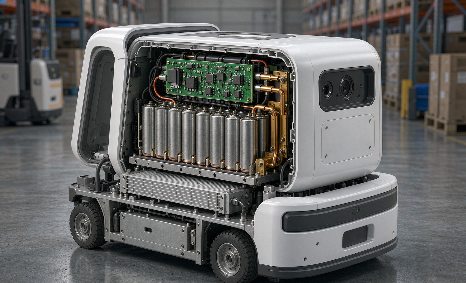
Mobile robots punish packs with vibration, shock, and constant micro-flexing, so format choice is a reliability decision, not just a volumetric one. Cylindrical 21700 cells with laser-welded pure-nickel busbars remain our default for robotics because the rigid steel can survives 1.2 grms of continuous vibration and survives drops that crack prismatic welds. We favor a module-less, cell-to-pack layout for lower mass, but keep a compliant silicone interlayer between cells and the housing to absorb shear. Prismatic cells suit large 48–80 V tuggers where volume is plentiful and cycle life is king. In every case the weld joint is qualified to a 4-wire Kelvin resistance below 0.15 mΩ and a pull strength above 25 N, because a fatigued weld is the most common field failure we see.
4. Electrical Architecture: Voltage Platform and Multi-Rail Power
Most AMRs standardize on 24 V or 48 V. We pick 48 V whenever the continuous load exceeds ~1 kW, because halving the current roughly quarters I²R copper loss in the harness. The pack is rarely the only load: lidar, compute, and actuators each want clean, isolated rails. We design the battery as a regulated power hub, adding synchronized buck converters for 5 V, 12 V, and 24 V auxiliary outputs, with soft-start MOSFETs that isolate payload inrush from the propulsion bus. A 60 W light bank that once caused a 1.4 V, 90 ms propulsion sag now draws only 0.3 V over 8 ms after isolation. We add pre-charge resistance on the main contactor to avoid welding the contacts, and a pyrotechnic or semiconductor fuse sized to clear a hard short within milliseconds.
5. Mechanical Design for Shock, Vibration, and Docking
A robot that docks twenty times a shift experiences a controlled collision every few minutes. We design the pack enclosure for that reality: a hard-anodized 6061-T6 cradle with peripheral crush cans that absorb docking energy before it reaches the cells, mounted on viscoelastic dampers tuned to the robot’s dominant 20–80 Hz vibration band. Gaskets are specified to IP54 as a floor for dusty warehouse floors, rising to IP67 for outdoor or wash-down units. We validate against ISO 3691-4 for industrial trucks and ISO/TS 15066 for collaborative operation, plus ANSI/RIA R15.06 for the cell containment margins. The connector is keyed and latched to survive 1,000+ mating cycles without a 0.5 mm shift in cell position.
6. BMS Design Built for Robotic Loads
A robotics BMS must do more than protect cells; it must speak the robot’s language. We run a dual-channel monitor with independent voltage and temperature sensing so a single sensor fault cannot mask an overtemperature event, and we gate contactors in under 200 ms on any trip. State-of-charge estimation uses a load-aware Kalman filter rather than a naive coulomb counter, because the irregular robotic profile otherwise drifts 8–12% per shift. State-of-power output feeds the robot a real-time “available pulse current” number so it can de-rate gracefully instead of browning out. Communication is CAN 2.0B (J1939/ISO 11783 style) so the fleet manager sees per-pack health, and we gate retirement on DCIR +30%, capacity below 85%, or cell-voltage spread above 40 mV.
7. Connectors, Field-Swap, and Fleet Standardization
For fleets, the pack that can be swapped in under ninety seconds keeps robots earning. We standardize on a single bay form factor so one custom battery solution serves mapping, lifting, and transport variants, and we engrave a DataMatrix code on every pack for genealogy tracking. Hard-gold 30 µin contacts outlast flash plating beyond 1,000 cycles while holding DCIR under 0.15 mΩ. We pair the mechanical swap with a one-button health gate at the charging station: a pack that fails the DCIR or spread check is quarantined automatically. Standardization also lets a second source qualify against the same mechanical and electrical interface, which is essential when a cell shortage would otherwise ground the fleet.
8. Standards and Certification Baseline
No robotics pack leaves the building without a complete evidence package. Transport and baseline safety rest on UN38.3 (T.1–T.8 altitude, thermal, vibration, shock, external short, impact, overcharge, forced discharge), IEC 62133-2 for portable lithium cells and batteries, IEC 62619 for industrial stationary and motive applications, and UL 2580 for batteries in electric vehicles. For the robot itself we align with ISO 3691-4, ISO/TS 15066, and ANSI/RIA R15.06. Air-freight variants stay under the 100 Wh or 160 Wh IATA Section II thresholds with state of charge capped at 30%, and we document FAA and EASA acceptance for any cross-border movement. Certification is the floor, not the finish line; our field-reliability gates sit well above the regulatory minimums.
A Worked Example: A 48 V 30 Ah AMR Pack
To make the method concrete, here is a pack we shipped for a 600 kg payload AMR. Duty cycle: 18 A continuous, 55 A 2 s pulses, opportunity charging during 8-minute breaks. We chose LFP 32140 cells for 4,000+ cycles, arranged 15S10P to hit 48 V nominal and 30 Ah. Pack DCIR lands at 9 mΩ, giving a worst-case sag of 0.5 V at pulse — comfortably inside the robot’s 1 V budget. A 4 mm aluminum spreader plus 1.5 W/m·K thermal interface material holds the center-cell gradient under 5 °C. Auxiliary 12 V and 24 V rails run off a 96% efficient sync-buck stage. The dual-channel BMS talks CAN at 500 kbps and retires packs at 80% capacity. The result is a battery solution that costs a little more up front and pays it back in under a year through avoided downtime.
Frequently Asked Questions
What chemistry is best for warehouse robotics batteries?
For 24/7 fleets where cycle life and safety dominate, LFP is usually best because its 3,000–6,000 cycles and stable chemistry cut lifetime cost. NMC wins when mass or volume is tightly constrained, and sodium-ion is worth evaluating for cold-climate or cost-sensitive fleets. The right answer comes from the duty cycle, not a spec-sheet default.
How do you size a robotics battery pack?
We size from logged current vs time: average current sets capacity with a 20–30% margin, peak current and pulse width set the DCIR budget so sag stays within the robot’s limit, and the charge window sets charge acceptance. We then add the auxiliary-rail loads and a thermal margin before finalizing the series-parallel arrangement.
Which standards apply to robotic lithium battery packs?
The core stack is UN38.3 T.1–T.8 for transport and safety, IEC 62133-2 for cells and batteries, IEC 62619 for industrial motive use, and UL 2580 for EV-class packs, layered with robot standards ISO 3691-4, ISO/TS 15066, and ANSI/RIA R15.06.
Why use a custom battery solution instead of an off-the-shelf pack?
Off-the-shelf packs rarely match a robot’s mechanical envelope, pulse profile, communication bus, and docking lifecycle. A purpose-built custom battery solution trims mass, eliminates inrush sag on the propulsion bus, and lets the fleet standardize one swappable form factor across many robot types, which lowers spare-parts inventory and downtime.
How long should a robotics battery last?
With LFP and disciplined 20–90% state-of-charge operation plus 4.10–4.15 V/cell charge caps, 3,000–6,000 cycles is realistic. We retire on health gates — DCIR +30%, capacity below 85%, or voltage spread above 40 mV — rather than on a fixed calendar date, which keeps healthy packs in service and grounds only the ones that truly need it.





