
Battery Solution Testing for Vehicles
When a customer asks Horizon Power to build a battery solution for a vehicle, the cell selection is only the first ten percent of the job. The other ninety percent is proving, with hard data, that the pack will survive ten years of potholes, desert heat, Scandinavian winters, and the occasional driver who never reads the manual. I am Karl Huang, Senior lithium battery Engineer, and over the last decade I have signed off on validation programs for everything from 48 V mild-hybrid modules to 800 V traction packs and ruggedized mining-vehicle batteries. This guide walks through the testing protocol we run before any custom battery solution leaves our factory for a vehicle application.
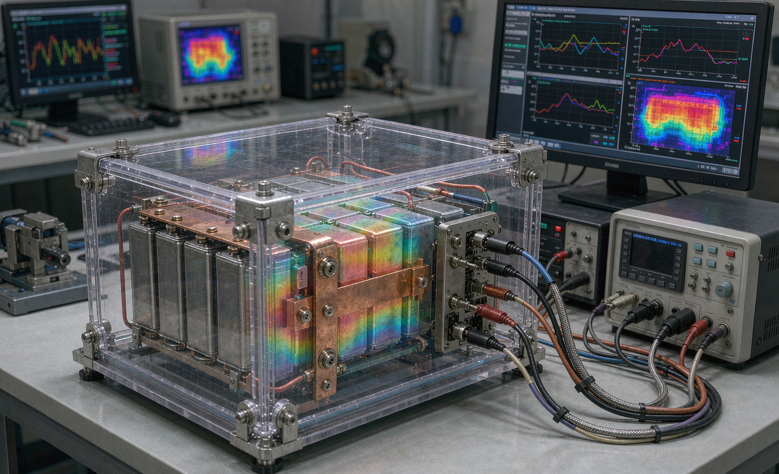
Vehicle duty is brutal in a way that consumer-electronics duty is not. A phone battery sees gentle 1C cycles on a desk. A vehicle lithium battery sees 5C discharges, regenerative 3C charges, sustained 70°C under-bonnet temperatures, and road vibration that will shake a loose busbar into a fire if you let it. Testing is how we find those weaknesses in the lab instead of in a customer’s warranty queue.
Why Vehicle Battery Testing Is a Different Discipline
The core difference between testing a battery for a vehicle and testing one for a stationary cabinet is the combination of high rate, safety-criticality, and mechanical abuse. A home energy wall can be swapped by a technician; a traction pack failure at 110 km/h cannot. That single fact reshapes the whole validation plan. We treat every vehicle program as a safety-critical program governed by automotive functional-safety thinking, even when the regulatory floor is lighter than the automotive standard.
Our baseline acceptance always starts at the universal transport and cell safety standards — UN38.3 (T.1–T.8 altitude, thermal, vibration, shock, external short, impact, overcharge, forced discharge) and IEC 62133-2 for the secondary cells — then layers the vehicle-specific standards on top. For a road-going EV we add UN R100 / ECE R100, IEC 62660 for traction cells, UL 2580 for the pack, and, when the pack ships with intelligence, ISO 26262 for functional safety.
Incoming Cell Grading: You Cannot Test Out a Bad Cell
Every validation program begins before assembly. We grade incoming cells from the supplier lot so that the pack we test is representative and consistent. Three numbers matter most: self-discharge, DCIR, and capacity.
- Self-discharge (K-factor): we store cells at 45°C for 7 days and require open-circuit voltage drift below 1.0 mV/day. A leaky separator shows up here first, months before it would matter in the field.
- DCIR: measured with a 4-wire Kelvin method at 50% SoC, 25°C, using a 10 s pulse. We bin to ±10% within a pack. Mismatched internal resistance is the fastest route to imbalance, local heating, and premature capacity fade.
- Capacity: 0.5C CCCV to 4.20°C cutoff at <0.05C, then discharged to 2.50°V. We bin packs to ±3% between parallel groups and ±6% across the whole shipment.
Only cells that pass grading go into the build we validate. This is also where a custom battery solution earns its name: the grading target is set by the vehicle’s duty cycle, not by a generic datasheet.
Electrical Performance: Capacity, Power, and the HPPC Pulse
Once assembled, the pack runs an electrical characterization matrix. We measure usable capacity at the vehicle’s actual C-rate (not the cell datasheet’s 0.2C), record discharge curves at 1C, 3C, and peak, and map DCIR across state-of-charge from 10% to 90%.
For power capability we run the Hybrid Pulse Power Characterization (HPPC) test: a 10 s discharge pulse followed by a 10 s regen pulse at each SoC step, every 10%. This gives the power envelope the vehicle controller will actually use for acceleration and braking energy recovery. A pack that looks fine at 1C can collapse at the 10 s pulse a downhill regen event demands, and HPPC is how we catch it.
We also verify the pack holds its rated capacity after a defined cycle life — typically 1,000 cycles at 80% DoD as an early gate, with the full 2,000-cycle target confirmed on representative samples. Any pack that drops below 80% SoH inside warranty is a failure we would rather find now.
Thermal Validation: From Cold Crank to Thermal Runaway
Vehicles live where people live, so we test the thermal envelope hard. Cold-crank simulation discharges at −30°C to confirm the pack still delivers cranking or launch power; hot soak at +85°C confirms the BMS and seals survive under-bonnet temperatures. Between them we run thermal shock: −40°C to +85°C, 50 cycles, with impedance checks before and after to catch delamination or weld fatigue.
The safety-critical end of thermal testing is propagation. Per UL 2580 and China’s GB 38031, we trigger a single cell into thermal runaway (heater or nail) and require that the event does not propagate to adjacent cells within a defined warning window, and that the pack emits no flame ejection through the enclosure. We instrument every cell with thermocouples and log the propagation time; a good design buys the vehicle minutes of warning, not seconds.
Mechanical Abuse: Vibration, Shock, and the Real Road
A vehicle battery is a structural component bolted to a chassis, so mechanical testing is non-negotiable. We run random vibration per ISO 16750-3 (road-load profile, three axes, roughly 8 hours per axis for passenger cars, longer for off-road and mining duty) and SAE J2380 for EV battery systemic vibration. Shock follows the same standard at 50 g half-sine. After vibration we re-torque every busbar and re-measure DCIR — a loose connection that the test “finds” is a real field failure prevented.
For rugged and industrial vehicles we add MIL-STD-810H-style drop and tumble, plus ingestion protection: IP67 (1 m water, 30 min) and, for exposed mounts, salt-spray per ISO 9227 to confirm the enclosure and connectors resist corrosion over the service life.
Safety, EMC, and Functional Safety Sign-Off
Electrical safety testing includes external short circuit (both terminals, per UN38.3 T.6), overcharge to 1.4× nominal with current limit, and forced discharge. We also perform dielectric withstand and insulation-resistance checks on the pack-to-chassis boundary — the numbers a service technician’s multimeter will depend on.
Because the pack talks to the vehicle, EMC matters. We screen against CISPR 25 for radiated and conducted emissions and run immunity per ISO 11452 so the battery does not both broadcast noise and crash when the radio key fobs. Finally, for any pack with a controllable BMS, we apply ISO 26262: we assign an ASIL, verify the safety concept (overvoltage, overtemperature, and isolation monitors), and document the fault-tree analysis. This is the part of a battery solution program that separates a component supplier from a true vehicle partner.
End-of-Line Burn-In and Field Correlation
Every production pack that passes validation still gets a final gate: a 72-hour burn-in at elevated temperature with a representative drive cycle, watching for voltage drift, temperature spread, and communication dropouts. Packs that pass ship; packs that drift get pulled and root-caused. We close the loop by feeding returned-field packs and warranty data back into the next validation plan — real fleets are the only test lab that runs for ten years.
Frequently Asked Questions
How long does a full vehicle battery validation program take?
A representative program runs eight to sixteen weeks. Cell grading and electrical characterization take one to two weeks; thermal and mechanical abuse testing overlap for four to eight weeks; safety abuse and EMC add another two to four. We compress schedules by parallelizing sample sets, but we never skip the propagation or vibration gates — those are where vehicle-specific failures live.
Which standards apply to a custom vehicle battery solution?
Always UN38.3 and IEC 62133-2 as the floor. For road EVs add UN R100 / ECE R100 and IEC 62660; for the pack add UL 2580 (North America) or GB 38031 (China); for functional safety add ISO 26262. Regional market and vehicle class change the exact list, which is why a custom battery solution is specified against the target certification from day one rather than tested afterward.
Can the same pack be used in a drone and a vehicle?
Rarely, and never without revalidation. A drone lithium battery is optimized for extreme power-to-weight and short cycles; a vehicle pack is optimized for energy, safety propagation, and mechanical durability. The duty cycles, standards, and enclosure requirements are different enough that we treat them as separate programs. The cross-link is useful for shared cell chemistry knowledge, not for shared certification.
What is the single most common failure we catch in testing?
Loose or under-torqued busbar connections that survive static checks but loosen under random vibration. It is why we re-torque and re-measure DCIR after the ISO 16750 vibration block. Catching it in the lab costs a rework hour; catching it in a customer’s vehicle costs a warranty campaign.
Do you test at the rated extreme temperatures or with margin?
With margin. We validate cold performance at −30°C even when the spec says −20°C, and hot soak at +85°C above a +70°C duty spec. The margin is the buffer for a vehicle parked in a real desert or a real Nordic winter, and it is non-negotiable for a safety-critical lithium battery application.





