
Battery Solution Integration for Equipment: An Engineer’s
Over the last decade I have integrated battery solution integration equipment for more than two hundred client programs at Horizon Power, from agricultural drones and warehouse robots to mobile medical carts and off-grid telecom nodes. The single biggest misconception I meet is that “the battery” is just a cell you bolt into a box. In reality, the cell is the easy part. The hard, value-adding part is the integration: making a pack survive the exact vibration, thermal, and regulatory envelope of the equipment it powers. A brilliant lithium battery cell becomes a liability the moment it is wedged into a chassis it was never designed for.
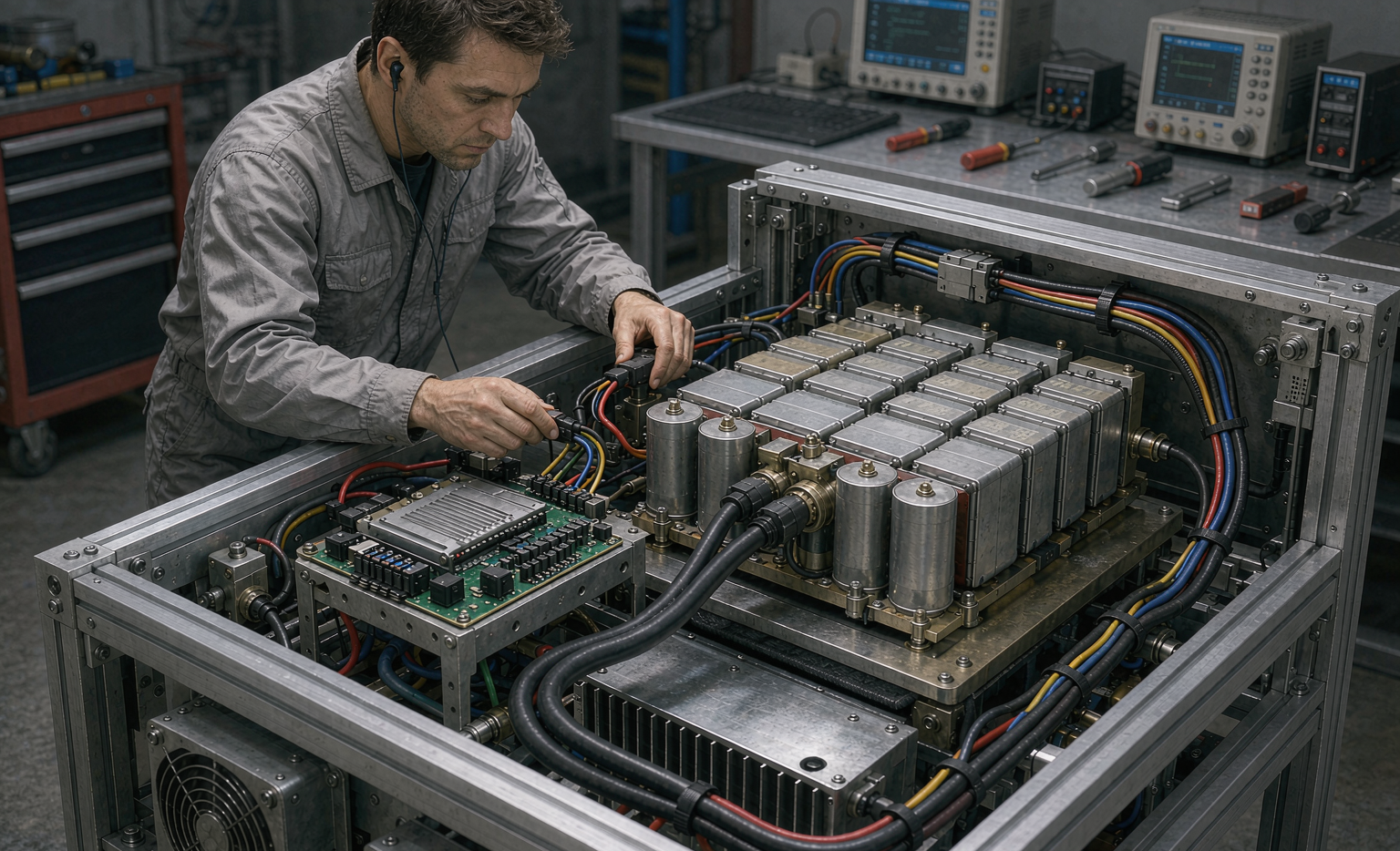
When a customer asks for a custom battery solution, what they are really buying is engineering certainty: that the pack will deliver rated energy on the coldest morning, that it will not trip the equipment’s inverter, and that it will clear customs and air freight without a rejection. This guide walks through the workflow my team uses, the standards we design against, and the trade-offs between chemistries.
Why Off-the-Shelf Cells Fail Inside Real Equipment
I once audited a floor-cleaning robot that kept shutting down after forty minutes even though its 18650 cells tested perfectly on the bench. The problem was integration, not chemistry. The pack sat two centimeters above a gear-motor that radiated 58°C; the battery’s internal resistance rose, voltage sagged under load, and the robot’s low-voltage cutoff fired early. No datasheet predicted this because datasheets assume a 25°C ambient. Real equipment is rarely 25°C.
Three failure modes dominate field returns: thermal crowding (pack too close to a heat source), mechanical resonance (a natural frequency that matches the equipment’s vibration spectrum), and connector fatigue (wires that flex ten thousand times). A battery application solution that ignores these will fail regardless of cell quality. We therefore start every project with a mechanical and thermal map of the host equipment, not with a cell selection.
The Integration Workflow: From Spec Sheet to Field Unit
Our standard engagement runs in five stages, each with a gate before we proceed:
- Load profiling. We log the equipment’s real current draw for a full duty cycle, capturing peaks the nameplate hides. A drone battery may draw 4C in a climb and 0.3C in loiter; a pack sized only for average current will sag on every takeoff.
- Envelope modeling. We build a CAD envelope of the battery cavity, including service clearance, connector reach, and vent paths.
- Cell and topology selection. Series-parallel arrangement is chosen to hit voltage and capacity while keeping peak cell temperature under 45°C in worst-case ambient.
- Prototype and abuse testing. We run short-circuit, crush, and overcharge on representative samples before any production commitment.
- Compliance and documentation. Test reports, UN38.3 summary, and labeling are finalized for global shipping.
This discipline is what separates a box of cells from a true battery solution. The workflow typically takes ten to fourteen weeks for a first field-ready unit, faster when we adapt an existing platform.
battery pack design for Mechanical and Thermal Fit
Good battery pack design begins with fixation, not electronics. We specify mounting that decouples the pack from the equipment’s primary vibration axis, using damped brackets rather than rigid clamps. For a handheld device, a 0.5 mm to 1 mm silicone gasket cuts transmitted shock by more than 30 percent in our drop tests.
Thermally, we design for the worst, not the average. Conduction paths move heat toward a chassis rail or external fin; in sealed units we use phase-change material pads rated for 5 W per cell of local dissipation. We also reserve headroom: a pack that runs at 80 percent of its thermal limit on day one will breach that limit after six months of calendar aging. I tell clients to design for the aged cell, not the fresh one.
BMS Solution: The Brain That Keeps Equipment Safe
The BMS solution is where most integration value lives. A bare protector IC only disconnects on fault; a proper BMS manages cell balancing, state-of-charge estimation, and communications with the host controller over CAN or SMBus. For equipment integration we almost always specify a topology-aware BMS that knows which cells are in series, so it can isolate a single failing group instead of killing the whole machine.
- Balancing current: 30–60 mA passive for low-cycle equipment; active balancing above 100 mA for high-throughput robots.
- SOC accuracy: we target ±3 percent across −10°C to 50°C using coulomb counting fused with a Kalman filter.
- Fault logging: the BMS records the last 200 events so field failures become diagnosable instead of mysterious.
For airborne platforms, the BMS must also meet the redundancy expectations of aviation authorities; we design dual-sense paths so a single sensor fault cannot mask an over-temperature condition.
Compliance You Cannot Skip: UN38.3, IEC 62133, FAA and EASA
No battery solution integration equipment program ships without transport and safety certification. UN38.3 is the baseline for lithium cells and batteries moving by air, sea, or road; it includes altitude simulation, thermal, vibration, shock, external short circuit, impact, overcharge, and forced discharge. I have seen shipments delayed for weeks because a UN38.3 test summary was missing a single signatory field.
For portable equipment, IEC 62133-2 governs the safety of lithium systems, covering abuse tolerance and cell-level protection. In the European Union, the BMS solution and pack must also align with the broader battery regulations and CE marking. For aviation-specific kit, FAA and EASA guidance drives additional design margins: venting must not impinge on structure, and isolation resistance is verified to documented thresholds. We keep a compliance matrix per program so nothing is discovered at the airline counter.
Cross-Chemistry Choices: Lithium, Semi-Solid, and Sodium-Ion
Chemistry selection is the final integration lever. A conventional lithium battery (NMC or LFP) remains the default for energy density and cost. Emerging semi-solid state battery chemistries push energy density higher while improving thermal stability, which simplifies the pack’s cooling burden. For cold-weather or cost-sensitive stationary loads, sodium-ion battery alternatives offer excellent low-temperature behavior and abundant raw-material supply, though at lower energy density.
Even home energy storage lessons apply to equipment: cycle life, calendar fade, and thermal runaway propagation are governed by the same physics. The integration question is always the same: which chemistry best fits this equipment’s duty, envelope, and market?
Connector, Communication, and Serviceability in the Field
Integration does not end when the pack physically fits. How the equipment talks to the battery, and how a technician services it in the field, decides whether the program actually scales. We standardize on locking, automotive-grade connectors rated for the equipment’s ingress class; a loose CAN connector on a vibrating platform is an intermittent-fault waiting to happen. For outdoor or wash-down equipment we specify IP67 interfaces even when the pack itself is sealed, because the connector is almost always the weakest link in the chain.
Communication matters for any battery solution integration equipment program that runs a fleet. A BMS that reports state-of-health over the network lets operators swap packs before they strand a machine on the floor. We expose a simple telemetry frame so the client’s software team can build dashboards without reverse-engineering a proprietary protocol. Serviceability is the final lever: we design packs a field technician can replace in under ten minutes with a single tool, because every minute of downtime is a cost the customer feels directly. A custom battery solution that forces a factory return for a single cell swap will quietly lose against a competitor’s swap-and-go design, even if its cells are marginally better.
FAQ
What does battery solution integration equipment actually involve?
It means engineering a complete power subsystem around a specific machine: cell selection, mechanical fixation, thermal management, a BMS, connectors, enclosure, compliance testing, and documentation. The deliverable is a drop-in pack that meets the equipment’s real operating envelope, not loose cells.
How long does a custom battery solution take to develop?
A first field-ready prototype usually takes ten to fourteen weeks including abuse testing and compliance prep. Adapting an existing validated platform can cut this to four to six weeks. Lead time is dominated by testing and certification, not by building the pack.
Can one battery application solution serve multiple equipment types?
Often yes, if the duty cycles and envelopes overlap. We design modular platforms where the cell block is shared and only the mechanical interface and BMS profile change. This lowers cost but requires disciplined variation control so a firmware mismatch never reaches the field.
How do I make sure the pack passes air shipping rules?
Build the UN38.3 dossier early, keep the test summary complete and signed, and label per the current IATA and IMO rules for the lithium content and watt-hour rating. We validate shipping classification before the first international shipment, not after a rejection at the dock.
What is the difference between a BMS solution and a simple protector?
A protector is a fuse-like safety switch that disconnects on fault. A BMS solution actively manages balancing, state-of-charge, and communication with the host, and logs faults. For any equipment with a duty cycle longer than a few minutes or a price above a few hundred dollars, a real BMS pays for itself in reliability.
Integration is where battery programs win or lose. Pick the right chemistry, design the pack for the aged cell and the real envelope, put a proper BMS in charge, and certify before you ship. That is the difference between a component and a dependable battery solution.





