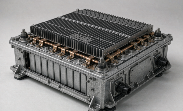
Battery Solution Deployment for Vehicles
I am Karl Huang, Senior lithium battery Engineer at Horizon Power, and over the last decade I have spent a surprising amount of my life in vehicle depots rather than in the lab. There is a particular moment I have learned to recognise: the design is frozen, the prototype has passed every bench test, the datasheet looks beautiful, and then the first ten vehicles roll into the workshop for installation — and nothing fits, or the alternator gets hot, or the truck’s gateway throws a fault code nobody has seen before.
That gap between a validated battery pack and a working vehicle is what battery solution deployment is about. It is not a logistics footnote. In my experience, deployment quality determines whether a vehicle battery solution delivers the cycle life we promised in the quotation, or whether it returns in eighteen months with a warranty claim we cannot honestly refuse. This guide walks through how I run a vehicle deployment: the electrical and mechanical audit, the mounting and integration rules, the network handshake with the vehicle, commissioning, fleet-scale rollout, and the compliance paperwork that has to travel with every pack. Everything here comes from programmes I have personally signed off on — light commercial vans, municipal service trucks, airport ground support equipment, and a few off-road platforms I am not allowed to name.
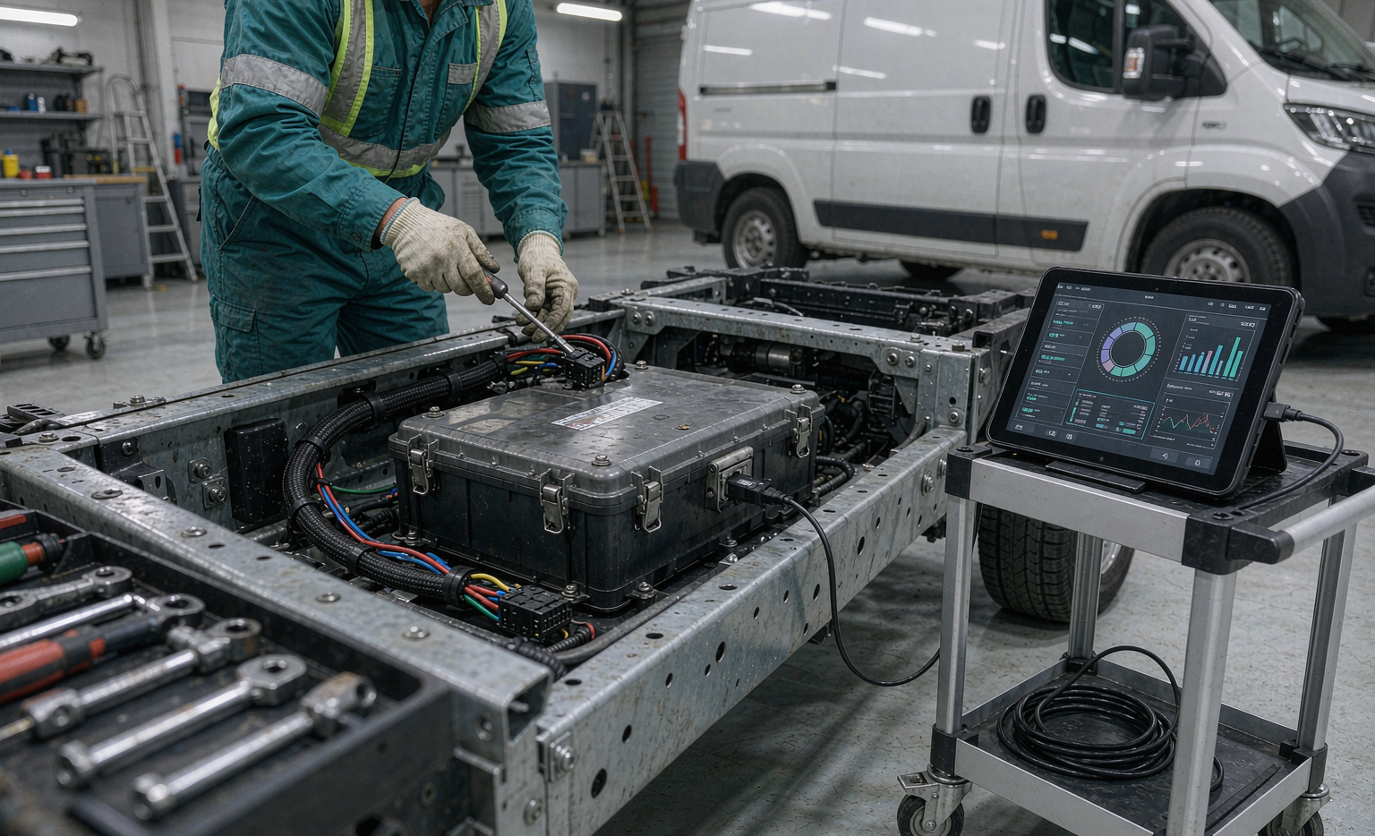
What deployment actually covers on a vehicle programme
Procurement teams tend to read “deployment” as shipping and bolting in. On a vehicle, it is five parallel workstreams, and any one of them can sink the schedule.
- Mechanical — envelope, mounting points, mass and centre of gravity, vibration and shock qualification, ingress and impact protection.
- Electrical — charge source sizing, cable cross-section, fusing and discrimination, grounding and bonding, insulation coordination, insulation resistance monitoring.
- Thermal — worst-case ambient, under-hood or underbody soak temperatures, solar load, cabin-air vs. dedicated cooling, cold-start heating.
- Data — vehicle bus integration (CAN 2.0B, SAE J1939, UDS, OBD-II), telematics backhaul, state-of-charge and state-of-health reporting, firmware update path.
- People — installer training, driver briefing, service procedure, spare-pool strategy, warranty registration, and an end-of-life return route.
The last one is the one that gets skipped, and it is the one that costs the most money later. A custom battery solution that is mechanically perfect but that a fleet mechanic cannot diagnose will be replaced prematurely, and the replacement will be blamed on cell quality.
Pre-deployment: audit the vehicle electrical architecture first
Before a single bracket is drawn, I insist on a two-hour audit per vehicle variant. The questions are boring and they catch roughly 80% of field failures before they happen.
Charge source: alternator, DC-DC, or shore power
The most common mistake I see is a lithium pack connected directly across a legacy lead-acid charging system. A conventional alternator is a constant-voltage source designed for a battery with a high internal resistance and a forgiving charge acceptance curve. A lithium pack has an internal resistance typically one-third to one-fifth that of an equivalent lead-acid bank, so it will pull current far beyond the alternator’s continuous rating. In one municipal truck programme, a 150 A alternator was delivering 190 A into a 5.2 kWh lithium battery pack and the stator winding reached 165 °C before the first week was out.
The fix is a dedicated DC-DC charger with a current limit set to roughly 60–70% of the alternator’s continuous rating, or an alternator with external temperature-compensated control. Practical numbers I work with: for a 12 V system, bulk 14.2–14.6 V with a 30–60 minute absorption window, float 13.5–13.6 V, and temperature compensation around −18 to −30 mV/°C referenced to 25 °C. Below 0 °C, charge current must be cut entirely or tapered to below 0.05C — plating metallic lithium on the anode is irreversible, it raises DC internal resistance, and it creates the nucleation site for an internal short.
Cable sizing and fusing
Voltage drop, not ampacity, usually governs. I design to a 3% drop on the main traction/auxiliary circuit and 1% on the sense leads, using the round-trip conductor length. For a continuous 200 A at 12 V over a 4 m round trip, that pushes you to 70 mm² copper; most installers quote 35 mm² because that is what the ampacity table says, and then the BMS under-voltage protection trips under load even though the pack is half full.
Every pack gets a fuse or a pyrotechnic-class DC contactor sized for the prospective short-circuit current of the pack, not just the load. A 5 kWh LFP pack at 12.8 V nominal can deliver several thousand amps into a bolted fault for a few milliseconds; an automotive blade fuse is not fast enough. I specify a Class T or an NH/gG-type DC fuse with an I²t rating verified against the pack’s own fault curve, and I always document the selective coordination so the pack fuse blows before the vehicle harness becomes the fuse.
Mechanical installation: mounting, vibration and ingress
Underbody and underfloor bays are the usual home for an auxiliary vehicle pack, and they are the harshest environment on the vehicle. The qualification envelope I hold installers to is ISO 16750-3 for mechanical loads and SAE J2380 for the random vibration profile specific to electric and hybrid battery systems; for heavier commercial platforms I add ISO 12405 or the customer’s own body-builder spec.
Mounting
Four rules I refuse to compromise on:
- Spread the load into structure, never into sheet metal. A 45 kg pack on a 2 mm floor pan will fatigue-crack the pan in 20,000 km. Use a sub-frame tied to chassis rails or to reinforced cross-members.
- Fastener class and torque are design parameters. I specify 8.8 or 10.9 metric fasteners, torque to 70–75% of proof load, and require a witness mark after re-torque at the first 1,000 km service. Nyloc or prevailing-torque nuts only — spring washers do not survive the vibration spectrum under a truck.
- Keep the pack inside the vehicle’s approved centre-of-gravity envelope. I have seen a roof-mounted auxiliary pack raise a high-top van’s CG enough to fail a lane-change test.
- Isolate galvanically where you can. A stainless bracket against an aluminium enclosure with road salt as the electrolyte will corrode. Nylon or EPDM isolators cost cents and prevent a warranty claim.
Ingress and impact
Underbody means pressure washing, salt spray and gravel. I spec IP66 minimum per IEC 60529, IP69K where the vehicle gets steam-cleaned, and IK08 or better per IEC 62262 for any surface exposed to stone strike. Connector choice matters more than the enclosure: on a fleet of winter-service trucks, the failures were never the cells, they were the unsealed Deutsch connectors on the BMS harness wicking water in by capillary action. Heat-shrink with adhesive liner and a drip loop below the connector body solved it.
Battery management and vehicle network integration
This is where a battery pack design proves whether it was engineered for a vehicle or merely placed in one. The BMS has to speak the vehicle’s language and behave predictably when the vehicle misbehaves.
Bus protocol and signal map
For light commercial vehicles I use CAN 2.0B at 500 kbit/s with an 11-bit or 29-bit identifier scheme agreed with the integrator; for heavy trucks and buses it is SAE J1939 with properly assigned PGNs and source addresses. The minimum signal set I insist on exposing:
- Pack voltage, pack current (signed), state of charge (±3% after a full charge calibration in the 20–80% window, degrading to ±5% at the ends).
- Minimum and maximum cell voltage, plus the cell ID for each, and the live cell delta in mV.
- Maximum and minimum cell/thermistor temperature, with thermistor location.
- Insulation resistance in Ω/V from the monitoring circuit.
- Fault and warning bitmaps, with a latch so a transient fault is still readable after the ignition cycle.
- State of health and cumulative amp-hour throughput.
A BMS solution that only reports “OK / FAULT” on a single wire is not acceptable for fleet service. Fifteen cells out of balance by 40 mV is a serviceable condition; the same pack six months later at 180 mV is a warranty event, and you can only tell the difference if you can see the delta.
Charge and load control logic
I configure the BMS to request, not command. The pack advertises its charge current limit (CCL) and discharge current limit (DCL) continuously, and the vehicle’s energy manager or the DC-DC charger respects them. When a cell hits the high-voltage protection threshold, the sequence is: taper request → if ignored for 5 s, open the charge path → latch a fault, log a snapshot of all cell voltages and temperatures at the trip instant. That snapshot is worth its weight in gold during a failure analysis, because it is the only record of pack state at the moment things went wrong.
Cold-weather behaviour deserves its own paragraph. Below 0 °C, charge is blocked; where the duty cycle requires winter operation I integrate a self-heating film or a PTC pad drawing 200–600 W, energised only when the pack is on shore power or when SoC is above a reserve threshold. I do not let a vehicle heater run the pack below 20% SoC in −20 °C ambient — I have seen packs pulled down into deep discharge by a cab heater overnight, and LFP cells discharged below 2.0 V at temperature rarely recover to specification.
Commissioning and acceptance testing
Every vehicle that leaves the depot gets a documented commissioning record. Mine runs to about 40 checks; the ones that matter most are these:
- Insulation resistance: measured at the pack’s maximum working voltage, using the ISO 6469-3 / ECE R100 criterion of 100 Ω/V minimum for DC circuits. On a 51.2 V LFP auxiliary pack that is 5,120 Ω — in practice a healthy pack measures in the hundreds of kΩ to MΩ, so anything under 100 kΩ gets investigated before the vehicle is released.
- Hipot / dielectric withstand: per IEC 62485 or the customer standard, typically 2U + 1000 V AC for 60 s on the pack-to-chassis path, applied once at commissioning and never repeated casually.
- Torque audit: every power terminal re-torqued and witness-marked, with the value recorded.
- Functional charge/discharge: one full cycle on the vehicle’s own charging system, logging CCL/DCL response and temperature rise at the terminals. Terminal temperature rise above 30 K over ambient at rated current means a crimp or a lug is wrong.
- Bus integration test: verify every PGN/signal appears correctly on the vehicle gateway, and verify the instrument cluster or telematics shows SoC.
- Fault injection: deliberately open a thermistor and confirm the vehicle shows a warning rather than silently continuing.
The last test is the one fleet operators thank me for eighteen months later. A fault path nobody has ever exercised is a fault path that will not work when it is needed.
Fleet-scale rollout: pilot, then ramp
Vehicle programmes fail at scale for reasons that have nothing to do with electrochemistry. The pattern I use now, after burning my fingers on a 400-unit rollout early in my career, is a staged ramp.
- Pilot, 5–10 units, 8–12 weeks. Deliberately choose the worst duty cycles: the longest route, the coldest depot, the driver who idles with every load on. Install telematics loggers that capture pack-level data at 1 Hz, not just the summary the fleet portal shows.
- Design freeze after pilot. Review every logged anomaly, fix the bracket, the harness, the charge curve, the driver procedure — then freeze. No changes during ramp unless a safety issue appears.
- Ramp in waves of 25–50, with a two-week observation window between waves. Wave 2 absorbs the lessons; waves 4+ become routine.
- Spare pool and RMA workflow. I hold spares at roughly 3% of installed base for the first year, with an advance-replacement agreement so a vehicle is never off the road waiting for a failure analysis.
- Training. Two audiences: installers get a half-day on torque, sealing and insulation testing; drivers get fifteen minutes on what the warning lamp means and what to do about it. Driver behaviour — leaving a load on overnight, ignoring a low-SoC warning — is a top-three cause of premature pack replacement.
Compliance and transport: the paperwork that travels with the pack
A vehicle battery solution is a regulated object from the moment it leaves the factory. The documentation set I hand over with every deployment:
- UN 38.3 test summary covering T1 (altitude), T2 (thermal cycling), T3 (vibration), T4 (shock), T5 (external short), T6 (impact/crush), T7 (overcharge) and T8 (forced discharge) — mandatory for any lithium cell or pack moving by any transport mode.
- IATA DGR / IMDG / ADR-RID shipping declaration. For air freight of a standalone pack (UN3480) the state of charge must not exceed 30%; for batteries installed in or packed with equipment the rules differ, and I have had entire consignments held at a European airport over that distinction.
- IEC 62619 for industrial and commercial vehicle auxiliary applications, and IEC 62133-2 where the pack falls into portable or light-vehicle scope.
- ECE R100 Rev.2 and ECE R10 for road-vehicle type approval in UNECE markets — the electrical safety and electromagnetic compatibility requirements respectively. Where the vehicle is an EV conversion or a hybrid, ISO 6469 parts 1–4 apply to the traction system.
- UL 2580 or UL 1973 for the North American market depending on whether the pack is a propulsion or a stationary/auxiliary battery.
- EU Regulation 2023/1542 — the digital battery passport obligations arriving for industrial and EV batteries from 2027. I already build the data model into every deployment record, because retrofitting traceability onto five years of shipped packs is far more expensive than capturing it now.
Service, health monitoring and end of life
Deployment is not over when the vehicle drives away. I set the following thresholds with fleet operators and review them quarterly:
- Capacity fade below 80% of nameplate, measured by a controlled discharge at 0.2C and 25 °C, triggers a health review.
- DC internal resistance growth above 1.3× the beginning-of-life value is an earlier and more sensitive indicator than capacity, and it usually shows up two to three quarters first.
- Resting cell delta above 50 mV on a pack that was balanced to under 15 mV at commissioning means passive balancing is no longer keeping up; the pack is telling you it is old.
- Any pack with a history of a thermal event, an insulation fault, or physical damage is retired regardless of measured capacity. I do not redeploy damaged packs into a second-life role on vehicles, even though the cells may test fine.
End of life is part of the deployment plan, not an afterthought. Return logistics, a documented route to a permitted recycler, and — under EU 2023/1542 — the recovery-efficiency reporting obligations for lithium, cobalt, nickel and copper. A fleet operator who cannot produce that paperwork at audit time will remember the name of whoever sold them the pack.
What I tell every customer before a vehicle deployment
Three things. First, the battery is the cheapest part of a failed deployment: the rework, the vehicle downtime and the lost trust cost ten to fifty times more than the pack. Second, spend the money on the audit, the bracket and the training before you spend it on more amp-hours — most “undersized battery” complaints I investigate are actually voltage drop, charge control or duty-cycle problems in disguise. Third, insist on data access. If you cannot read cell voltages and insulation resistance from your own fleet, you are not managing a battery asset, you are waiting for it to fail.
The same engineering discipline applies whether the pack is going into a delivery van in Rotterdam, a ground-support tug at an airport, or a drone battery pack for an inspection platform — the loads differ, the physics does not. Get the charge control right, mount it into structure, seal the connectors, log the data, and the pack will deliver the cycle life your quotation promised.
FAQ
How long does a vehicle battery solution deployment take from order to first vehicle?
For a custom battery solution on an existing vehicle platform, I plan on 10–14 weeks: 2 weeks for the electrical and mechanical audit, 4–6 weeks for pack design and sample build, 2–3 weeks for bench qualification, and 2–3 weeks for the pilot installation and commissioning. Fleet ramp then proceeds at whatever rate the workshop can absorb — realistically 25–50 vehicles per week per installation bay.
Can a lithium battery pack replace a lead-acid bank directly without changing the charging system?
Almost never safely. A lithium pack’s low internal resistance will pull current far beyond an alternator’s continuous rating, and lead-acid charge profiles include an equalisation or desulphation mode at 15 V or higher that will trip a lithium BMS over-voltage protection or, worse, damage cells. You need a lithium-compatible DC-DC charger or a reprogrammed alternator regulator, plus low-temperature charge cut-off.
What vibration standard applies to a battery pack installed in a commercial vehicle?
ISO 16750-3 is the baseline for mechanical loads on vehicle electrical equipment, and SAE J2380 gives the random vibration profile specific to battery systems. For heavier commercial platforms I add the customer’s body-builder specification or ISO 12405. Whichever applies, the test must be run on the pack mounted in its production bracket, not strapped to a shaker table — the bracket changes the resonant frequencies completely.
How cold is too cold for charging a vehicle lithium battery?
Charging below 0 °C causes lithium plating on the anode, which is irreversible and raises the risk of an internal short. A cold-weather pack needs an integrated heater and a BMS that blocks charge current until cells are above roughly 5 °C, tapering current between 5 °C and 15 °C. Discharge is more forgiving — LFP will deliver current down to −20 °C, but available capacity drops to roughly 60–70% of the room-temperature figure at that temperature.
What state of charge must a battery pack be shipped at?
For standalone lithium-ion packs shipped by air (UN3480) the IATA Dangerous Goods Regulations cap state of charge at 30%. Batteries installed in or packed with equipment follow different packing instructions. By road under ADR, or by sea under IMDG, the SoC restriction does not apply in the same way, but the UN 38.3 test summary and the dangerous goods declaration are required for every mode.
How many cycles should a vehicle auxiliary lithium battery deliver?
For a properly deployed LFP pack at 25 °C, 0.5C charge and discharge, and 80% depth of discharge, I specify and routinely measure 3,000–4,000 cycles to 80% capacity retention. NCM packs give roughly 1,500–2,500 cycles in the same duty but at higher specific energy. Real fleet numbers are usually lower than the datasheet — not because the cells are worse, but because deep discharges, high ambient temperatures and fast charging all accelerate fade.
What causes a battery pack to fail in the field most often?
In my warranty data, in order: connector and harness ingress, loose or under-torqued power terminals, charge control mismatch with the vehicle’s charging system, and only then cell-level defects. A robust deployment process addresses the first three completely, which is why I weight installation quality so heavily.
Do I need a separate battery management system if the vehicle already has an energy manager?
Yes. The BMS is a safety device that belongs to the pack — cell balancing, cell-level voltage and temperature protection, insulation monitoring, contactor control. The vehicle energy manager is a supervisory controller that allocates power. The BMS publishes its limits; the vehicle respects them. Collapsing the two into one controller creates a single point of failure on a safety function, which no functional-safety assessment will accept.