
Battery Solution Safety for Vehicles: An Engineer’s (2)
I have spent fifteen years signing off on traction packs, and the pattern is always the same: the pack that fails in the field was never killed by one dramatic mistake. It was killed by four small ones that lined up — a busbar that was never re-torqued, a vent sized by rule of thumb instead of by gas-generation data, a BMS whose overvoltage trip shared a microcontroller with the state-of-charge estimator, and a service manual that told a technician to wait two minutes when the real discharge time was six. Every one of those is boring. Together they put a vehicle on fire.
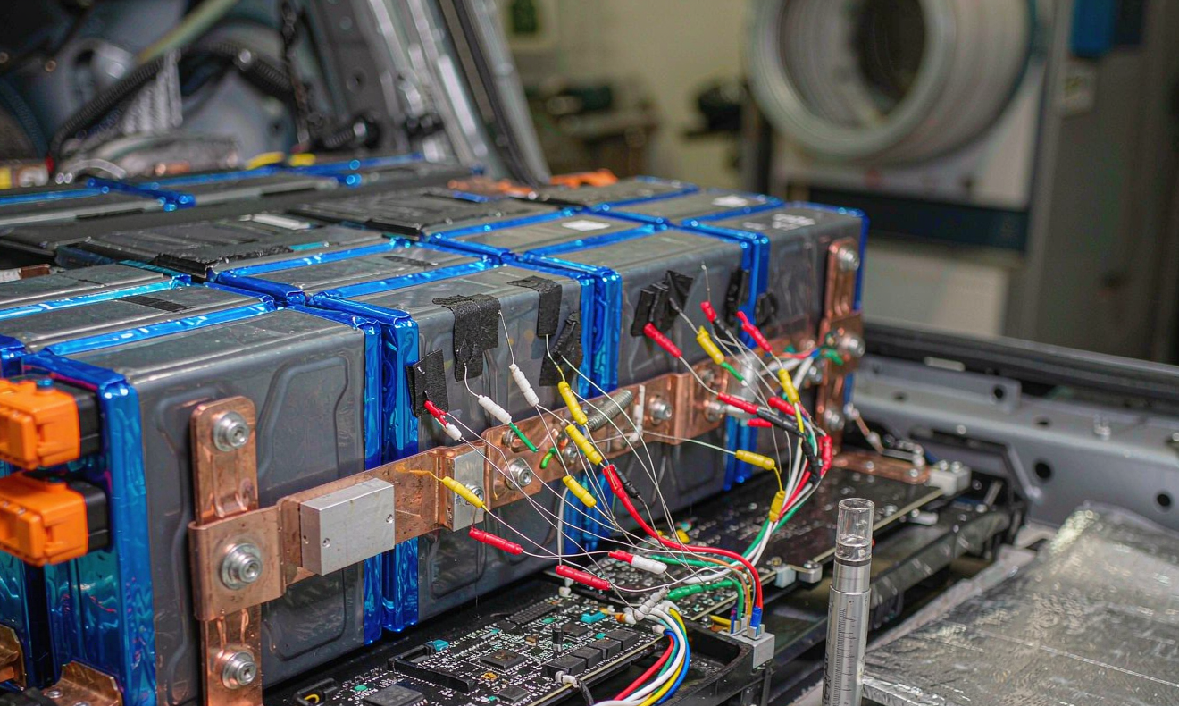
This piece is the safety review I run on any vehicle battery solution before it leaves my bench. It is written for people specifying or integrating packs into industrial vehicles, low-speed electric vehicles, utility and municipal fleets, and off-highway machinery — not for cell chemists. It covers chemistry selection, the mechanical and electrical margins that actually matter, the thermal-propagation test that decides whether a design is certifiable, the BMS architecture that keeps a single software bug from becoming a fire, the certification stack, and what your service team must do after delivery. Because in the end, battery solution safety for vehicles is not a certificate on a wall. It is a set of decisions that hold up on the worst day of the vehicle’s life.
What “Safe” Actually Means for a Vehicle Battery Solution
The first thing I do in a safety review is force the team to define the failure we are designing against. There are three distinct ones, and they need different defences.
The slow degradation failure. A pack that loses capacity, drifts out of balance, or silently grows internal resistance until the vehicle cannot finish a shift. Nobody gets hurt, but the fleet is down and the warranty bill is real. This one is caught by trending DCIR and cell-voltage divergence, not by safety devices.
The single-point electrical failure. A welded contactor, a chafed harness, a coolant leak onto a busbar. This is where creepage and clearance, insulation monitoring, and a properly rated pyrotechnic disconnect earn their cost.
The thermal-propagation failure. One cell vents, and the vent gas and heat cook its neighbours until the whole module is involved. This is the one that makes the news, and it is the one regulators now test directly.
A credible custom battery solution for a vehicle addresses all three with independent mechanisms. If your design relies on the BMS to prevent all three, you do not have a safety architecture — you have a single point of failure with a nice enclosure around it.
The Voltage Threshold That Changes Everything
Before anything else, establish whether you are building a high-voltage system. Under ECE R100 and ISO 6469, the boundary sits at more than 60 V DC or more than 30 V AC. Below that you are in low-voltage accessory territory. Above it, you inherit insulation-resistance monitoring, HVIL (high-voltage interlock loop), orange harness rules, service disconnects, and touch-protection requirements. A 48 V forklift pack and a 400 V utility-vehicle pack are not the same engineering exercise, and I have watched teams lose six months applying 400 V discipline to a 48 V product, or worse, applying 48 V habits to a 400 V one.
Chemistry: Choosing the Baseline You Can Defend
My default for vehicle traction is lithium iron phosphate. Not because it is fashionable, but because the numbers hold up under audit. In nail-penetration testing at 100 % state of charge, an LFP prismatic cell in the 100–280 Ah class typically peaks around 180–250 °C at the vent and does not propagate to its neighbours when a 1–2 mm mica or aerogel barrier sits between cells. The same test on a nickel-rich NMC cell reaches 500–700 °C and will propagate through six cells in under two minutes with no barrier at all.
LFP gives up energy density to get there: roughly 160–190 Wh/kg at cell level versus 220–260 Wh/kg for NMC, and around 300–360 Wh/kg for the semi-solid cells now reaching my bench. Cell-to-pack gravimetric overhead for a steel-shelled, liquid-cooled pack runs 30–35 %, so a 190 Wh/kg LFP cell lands near 130 Wh/kg at pack level. That arithmetic is fine for a municipal utility vehicle, a campus shuttle, or a warehouse tug. It is not fine for a long-range road vehicle, and pretending otherwise is how you end up deleting thermal barriers to hit a range target.
When a customer genuinely needs the energy density, I use this rule: NMC is acceptable when the pack has a rigid, vented, thermally isolated enclosure and a validated propagation barrier; semi-solid is acceptable when the programme can live with a second-source fallback on a pin-compatible LFP design, because early semi-solid lines still run at 82–88 % yield against 96 %+ for mature LFP. Whichever you pick, the cell date code must be under nine months old at goods-in, and the first article must come with an X-ray and a DCIR curve taken at three temperatures and three states of charge.
Mechanical and Electrical Margins That Survive a Vehicle
Vehicle duty is vibration duty. Before any electrical testing, I put the pack through 5–500 Hz at 3 g RMS for two hours per axis, then 30 g for 11 ms in six directions, then a 1 m drop onto each of six faces for packs that can be removed by hand. Acceptance is a DCIR shift of less than 15 %. Anything more and a busbar joint has already started to fret, and fretting joints do not heal — they only get worse at the worst possible moment.
On the electrical side, these are the numbers I hold the line on:
- Busbar joints. Welded below roughly 100 A continuous, bolted above it. Bolted M6 joints get 8–10 N·m, M5 gets 4–6 N·m, M8 gets 12–14 N·m, every one paint-marked after torque. Nickel-plated copper, never bare copper in a humid bay.
- Contactors. Rated at least 1.5× continuous current, with welded-contactor detection on every pack. A contactor that welds closed is invisible to the driver and catastrophic to the technician.
- Precharge. Mandatory above 60 V. For a 400 V system with a 1000 µF DC-link, a 100 Ω precharge resistor gives τ = 0.1 s and a full precharge in about 0.3 s, dissipating roughly 80 J — so a 5 W resistor is nowhere near adequate for repeated cycles. Size the resistor on energy, not on time.
- Creepage and clearance. Per IEC 60664 for the working voltage and pollution degree. On a 400 V nominal pack I want clearances in the 3 mm range and creepage around 4 mm or better, with a conformal coating on the BMS if the enclosure is anything below IP65.
- Ingress. IP67 minimum for underfloor or exterior mounting, IP6K9K if the vehicle is washed with pressure or works in mud. I have opened more packs killed by a pressure washer than by rain.
- Thermal operating window. Cell surface at 45 °C or below continuous and 55 °C or below peak. Every 10 °C above that roughly halves LFP calendar life, which is a slow failure that shows up as a warranty claim three years later.
The Thermal-Propagation Test That Decides Everything
Since the second revision of ECE R100 and the introduction of GB 38031, the requirement is explicit: after a thermal event is triggered in the pack, occupants must have at least five minutes of warning before fire or explosion enters the cabin. Five minutes sounds generous until you run the test and watch a barrier-less NMC module reach propagation in ninety seconds.
My protocol is deliberately conservative. I trigger with a nail at 100 % state of charge on a cell in the geometric centre of the pack — the worst location, not the most convenient one. Instrumentation is thermocouples on every neighbouring cell plus a gas sensor in the pack headspace. Pass criteria: no fire exits the enclosure, adjacent cell peak temperature stays below the point where its own separator shutdown activates, and the BMS raises a warning within 60 seconds of the trigger.
The barrier is doing most of the work. A 1–2 mm mica sheet or an aerogel blanket between cells, combined with a compression pad that keeps the stack loaded, buys the minutes you need. Pack venting is the other half, and I size it from data rather than intuition: an NMC cell vented at 100 % SoC generates roughly 0.02–0.05 L of gas per Wh of capacity — mostly CO₂, CO, HF and electrolyte vapour. Take the worst case for the number of cells that can vent, and size the vent to keep internal overpressure under 10–20 kPa so the enclosure does not rupture at its seams. A vent that is too small turns a contained event into an enclosure failure.
BMS Architecture: Assume the Software Is Wrong
I design every vehicle BMS on the assumption that the state-of-charge estimator will, at some point, be wrong. That means protection and estimation cannot live on the same path.
The primary protection path is a dedicated analogue front-end with hardware comparators for cell overvoltage, cell undervoltage, overcurrent and overtemperature. It trips the contactors without asking the microcontroller for permission. The microcontroller handles SoC, balancing, logging and CAN telematics. If the firmware hangs, the pack still opens its contactors. On safety-critical programmes this architecture is what gets you to ISO 26262 ASIL C on the pack control unit, and trying to reach that rating with a single shared path is a fight you will lose.
The rest of the safety chain:
- HVIL. A low-current loop through every service disconnect and connector, broken in under 10 ms when anything is unplugged, dropping the contactors with it.
- Insulation monitoring. Continuous measurement of DC bus resistance to chassis. ECE R100 wants at least 100 Ω/V on the DC side and 500 Ω/V on the AC side; I alarm at five times the minimum so there is margin to investigate before it becomes a trip.
- Pyrotechnic disconnect. On airbag-deploy or severe-crash detection, a pyrofuse opens the pack in under 5 ms. A mechanical contactor is far too slow for a crash pulse.
- Event log. Non-volatile, tamper-evident, at least 500 events with timestamps. When something goes wrong in year four, this log is the only honest witness you have.
Certification: The Stack, and the Order to Run It
Sequence matters more than most teams expect, because a failure late in the stack is expensive. My order:
- UN38.3 — transport. Eight tests, and half of them are paperwork. Run this early because nothing ships without it.
- IEC 62660-2 and -3 — cell-level reliability and abuse, plus electrical and thermal performance. This is where a marginal cell source is exposed.
- IEC 62133-2 — cell and battery safety for the pack as a product where applicable.
- ECE R100.02 or GB 38031 — the vehicle-level electrical safety and thermal-propagation requirements for your target market.
- ISO 6469-3 and -4 — electrical safety and post-crash safety requirements, which drive the service documentation as much as the hardware.
- UL 2580 for North America, and UL 9540A data if the vehicle is stored or charged inside a building alongside other equipment.
Budget six weeks from first article to a complete file, and do not start the mechanical abuse testing until the electrical baseline is stable. I have seen teams burn three sets of prototypes by reversing that order.
After Delivery: Where Vehicle Safety Is Really Won
The most under-funded part of every programme I review is the post-delivery safety procedure. A pack can be beautifully engineered and still be destroyed in year two by a technician who does not know the discharge time.
What every service document must state in plain language: the HV service disconnect location and how to verify zero energy with a CAT III 1000 V meter, the measured discharge time after key-off (on a 400 V pack with a 1000 µF DC-link and bleeder resistors, that is typically two to six minutes — not the thirty seconds people assume), the PPE and insulated tool requirement, and the rule that no one works on a live pack alone.
Then the maintenance cadence. Monthly: visual inspection, connector and gland check, cell-voltage divergence below 30 mV at rest (50 mV is a yellow flag, 100 mV is a stop-work item). Quarterly: DCIR on a 0.5C 10-second pulse against an 18–22 mΩ baseline, where a 30 % rise is a yellow flag and a 50 % rise means the module leaves service; plus torque re-verification on every marked joint. Annually: a 0.2C capacity test with an 80 % end-of-life threshold, an insulation-resistance check at 500 V with anything under 1 MΩ investigated, and a firmware review.
Storage and transport are their own discipline: 30–50 % state of charge, 10–25 °C, top up every 90 days, and never ship a pack above 30 % SoC under UN38.3 unless the shipper’s documentation explicitly permits it.
FAQ
Is LFP always the safe choice, or are there cases where I should not use it?
There are two. If your vehicle has a hard volume or mass ceiling that LFP cannot meet — a road-legal passenger platform with an aggressive range target, for example — then a high-nickel cell with a validated propagation barrier is the honest answer, provided you test it rather than assume it. And if the vehicle operates below −20 °C without a thermal-management system, LFP’s cold-weather discharge and charge-acceptance limits make it a poor fit; sodium-ion or a heated pack is the better call.
Do I really need a pyrotechnic disconnect on an industrial vehicle that never exceeds 40 km/h?
If the pack is above 60 V DC and the vehicle operates where people can be near it during a crash, yes. Speed is not the deciding factor — the crash pulse duration is. A pyrofuse opens in under 5 ms; a contactor needs tens of milliseconds and may weld. The cost is a few tens of dollars against a failure mode you cannot mitigate any other way.
How long should a vehicle pack last before it is no longer safe, even if capacity is fine?
Capacity is not a safety metric. I use three retirement triggers: DCIR up more than 50 % from baseline, measured capacity below 80 % of nominal, or any physical damage to the enclosure or cell stack. In a typical one-shift-per-day industrial duty cycle that puts the honest service life at 7–9 years to 75–80 % capacity, with a mid-life refurbishment around year five — torque audit, connector replacement, fan and filter change, thermal interface renewal — at roughly 40 % of replacement cost for another five years.
What is the single most common safety defect you find in reviews?
Undersized or absent pack venting, followed closely by bolted busbars with no documented torque value and no paint mark. Both are invisible in a datasheet, both pass a functional test, and both show up in year three. The fix costs almost nothing at design time and is a full pack redesign after launch.
Can a BMS firmware update improve safety, or does it just add risk?
Both. Firmware updates fix real defects — I have closed a false overvoltage trip that was grounding vehicles unnecessarily, and tightened a cold-charge limit that was allowing lithium plating at −5 °C. But every update must be regression-tested against the hardware protection path, and the pack must fail safe if the update is interrupted. Never let an update touch the primary protection comparators.
What should I ask a battery supplier before signing off on a vehicle programme?
Five things: cell date codes under nine months at delivery; the full UN38.3 test summary and IEC 62660-3 abuse report for the exact cell and mechanical design being shipped; the thermal-propagation test data for the actual pack, not a representative module; DCIR curves measured at three temperatures and three states of charge on the production batch; and a written statement that the BMS register map is open. A supplier who will not provide those has told you what you need to know.





